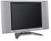
Sharp LC20B6US LC-20B6U-S Operation Manual - Page 10
Preparation Continued
 |
UPC - 074000362291
View all Sharp LC20B6US manuals
Add to My Manuals
Save this manual to your list of manuals |
Page 10 highlights
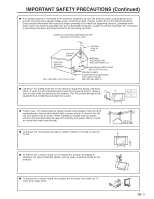
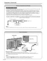
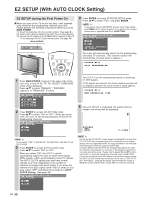
Preparation (Continued) Antenna Connection ANTENNAS • The antenna requirements for good color television reception are more important than those for black & white television reception. For this reason, a good quality outdoor antenna is strongly recommended. The following is a brief explanation of the type of connections that are provided with the various antenna systems. 1. A 75-ohm system is generally a round cable with F-type connector that can easily be attached to a terminal without tools (not supplied). F-type connector 2. A 300-ohm system is a flat "twin-lead" cable that can be attached to a 75-ohm terminal through a 300/75-ohm adapter (not supplied). 75-ohm coaxial cable (round) 300-ohm twin-lead cable (flat) OUTDOOR ANTENNA CONNECTION • Use one of the following two diagrams if you connect an outdoor antenna. A: Using a VHF/UHF combination outdoor antenna B: Using separate VHF and/or UHF outdoor antennas • Connect the outdoor antenna cable lead-in to ANT. (Antenna terminal) on the rear of the main unit. A. Combination VHF/UHF Antenna VHF/UHF antenna 300/75-ohm adapter (not supplied) VHF/UHF antenna or 300-ohm twin-lead 75-ohm coaxial cable Antenna cable (supplied) ANT. (Antenna terminal) B. Separate VHF and/or UHF Antennas UHF antenna VHF 300-ohm antenna twin-lead Combiner (not supplied) OUT IN 300-ohm twin-lead 75-ohm coaxial cable or NOTICE F-type connector F-type connector should be finger-tightened only. 75-ohm coaxial cable When connecting the RF cable to the LCD TV set, do not tighten F-type connector with tools. If tools are used, it may cause damage to your LCD TV set. (The breaking of internal circuit, etc.) Removing the Terminal Cover ■ Before connecting cables and cords to the rear terminals, remove the terminal covers. Push in the tabs and pull out the terminal covers carefully. ■ To mount the cover, insert the 2 hooks on the bottom of the cover into the cabinet and press on the upper part of the terminal cover until the tab locks in place with a click. 9
-
 1
1 -
2
-
3
-
4
-
 5
5 -
 6
6 -
 7
7 -
 8
8 -
 9
9 -
 10
10 -
 11
11 -
 12
12 -
 13
13 -
 14
14 -
 15
15 -
16
-
17
-
18
-
19
-
20
-
21
-
22
-
23
-
24
-
25
-
26
-
27
-
28
-
29
-
30
-
31
-
32
-
33
-
34
-
35
-
36
-
37
-
38
-
39
-
40
-
41
-
42
-
43
-
44
-
45
-
46
-
47
-
48
-
49
-
50
-
51
-
52
-
53
 |
 |
