Sony CDP-C79ES Operating Instructions - Page 5
Connections
 |
View all Sony CDP-C79ES manuals
Add to My Manuals
Save this manual to your list of manuals |
Page 5 highlights
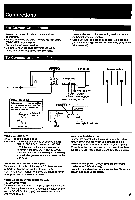
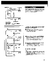
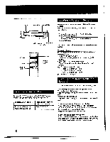
Connections For Correct Connections • Turn off the power of each unit before making connections. • Be sure to remove the transit key and red lock screw (CDP-C89ES only). (page 2) • Connect the AC power cord last. • Be sure to insert the plugs firmly into the jacks. Loose connection may cause hum and noise. To Connect to an Amplifier LINE OUT * • Leave a little slack in the connecting cord to allow for inadvertent shock or vibration. • Cord plugs and jacks are color coded: Red plugs and jacks are for the right channel (R) and white ones for the left channel (L). CDP-C89ES Speaker system To AC outlet / Optical Digital Out When connecting to an amplifier or D/A converter with OPTICAL IN, use OPTICAL DIGITAL OUT instead of LINE OUT. Take off the cap LISILIza Plug in firmly I. NTROL S OUT*3 NTROL S IN*2 SERIAL CHAIN MODE*4 SERIAL CHAIN Jerminal*4 SPEAKER Amplifier To wall outlet *lNotes on LINE OUT FIXED: The output level is fixed. VARIABLE: The output level can be adjusted with LINE OUT/PHONE LEVEL control or LINE OUT LEVEL buttons on the remote commander. However, if the LINE OUT/PHONE LEVEL control is turned while recording, the recording level will change even when it is preset on the tape deck. *2Note on the CONTROL S IN (Input) To remote control this unit through a CD player, receiver or amplifier, connect the input on this unit to the CONTROL S OUT (output) on a Sony CD player, receiver or amplifier, with a CONTROL S cable. *3Note on the CONTROL S OUT (output) (COP-CMS only) To remote control another CD player (supporting the Serial Chain feature) through this unit, connect the output on this unit to CONTROL S IN (input) on the other unit with a CONTROL S cable. Note on optical digital out Connect the optical out to the amplifier with the optical input or D/A converter. When you connect, use the connecting cable for optical out POC-15 (not supplied). When the optical out is connected, you cannot use fade out, fade in, DSP mode, level file and time fade function. *4Note on the SERIAL CHAIN terminal and MODE selector (CDP-C89ES only) Use both serial chain terminals to control two CD players serially. See page 28 for details. 5
-
 1
1 -
 2
2 -
 3
3 -
 4
4 -
 5
5 -
 6
6 -
 7
7 -
 8
8 -
 9
9 -
 10
10 -
 11
11 -
12
-
13
-
14
-
15
-
16
-
17
-
18
-
19
-
20
-
21
-
22
-
23
-
24
-
25
-
26
-
27
-
28
-
29
-
30
-
31
 |
 |
