Sony CDX-M800 Service Manual - Page 10
MOTOR BLOCK ASSY, CAM (R) ASSY, MAIN BOARD, the cam fully rotated in
 |
View all Sony CDX-M800 manuals
Add to My Manuals
Save this manual to your list of manuals |
Page 10 highlights
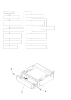
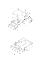
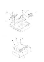
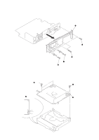
CDX-M800 2-4. MOTOR BLOCK ASSY, CAM (R) ASSY Note : Install the motor block assy and cam (R) assy in this roder. For phase alignment between cams (L) and (R), see page 15 and 17. 4 PTT 2.6x6 5 motor block assy 1 PTT 2.6x6 Note: Install the cam (R) assy with the cam fully rotated in the direction of the arrow A. A 3 CNP902 2 cam (R) assy 2-5. MAIN BOARD 5 MAIN board 3 PTT 2.6x6 ground point 4 PTT 2.6x6 ground point 2 PTT 2.6x6 1 PTT 2.6x6 10
-
 1
1 -
2
-
3
-
4
-
 5
5 -
 6
6 -
 7
7 -
 8
8 -
 9
9 -
 10
10 -
 11
11 -
 12
12 -
 13
13 -
 14
14 -
 15
15 -
16
-
17
-
18
-
19
-
20
-
21
-
22
-
23
-
24
-
25
-
26
-
27
-
28
-
29
-
30
-
31
-
32
-
33
-
34
-
35
-
36
-
37
-
38
-
39
-
40
-
41
-
42
-
43
-
44
-
45
-
46
-
47
-
48
-
49
-
50
-
51
-
52
-
53
-
54
 |
 |

10
CDX-M800
2-4. MOTOR BLOCK ASSY, CAM (R) ASSY
Note :
Install the motor block assy and cam (R) assy in this roder.
For phase alignment between cams (L) and (R), see page 15 and 17.
2-5. MAIN BOARD
1
PTT 2.6x6
4
PTT 2.6x6
5
motor block assy
2
cam (R) assy
3
CNP902
A
Note: Install the cam (R) assy with
the cam fully rotated in the
direction of the arrow
A
.
4
PTT 2.6x6
ground point
3
PTT 2.6x6
ground point
1
PTT 2.6x6
5
MAIN board
2
PTT 2.6x6