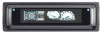
Sony CDX-M800 Service Manual - Page 5
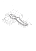
TABLE OF CONTENTS, 10. Shaft Roller Assy, Load SW Board - wiring diagram
 |
View all Sony CDX-M800 manuals
Add to My Manuals
Save this manual to your list of manuals |
Page 5 highlights
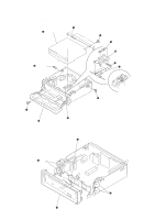
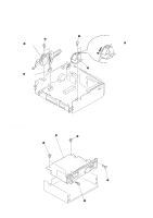
CDX-M800 TABLE OF CONTENTS 1. GENERAL Location of Controls 6 Connection example (US, Canadian Model 6 Connections (US, Canadian Model 7 2. DISASSEMBLY 2-1. Front Panel Assy 8 2-2. CD Mechanism Block, Front Panel Assy 9 2-3. Sub Panel (CD) Sub Assy 9 2-4. Motor Block Assy, Cam (R) Assy 10 2-5. Main Board 10 2-6. Heat Sink 11 2-7. Chassis (T) Sub Assy 11 2-8. Lever Section, In Self SW Board 12 2-9. Servo Board 12 2-10. Shaft Roller Assy, Load SW Board 13 2-11. Floating Block Assy 13 2-12. Optical Pick-up Block 14 3. PHASE ALIGNMENT 3-1. Arm (A-L) Assy, Arm (B-L) Assy 15 3-2. Cam (L 15 3-3. Motor Block 16 3-4. Alignment between Arm (A-L) Assy and Arm (B-L) Assy 16 3-5. Arm (A-R) Assy, Arm (B-R) Assy 17 3-6. Cam (R 17 4. DIAGRAMS 4-1. IC Pin Descriptions 18 4-2. Block Diagram -CD Section 21 4-3. Block Diagram -Tuner Section 22 4-4. Block Diagram -Display Section 23 4-5. Circuit Boards Location 24 4-6. Schematic Diagram -CD Mechanism Section 25 4-7. Printed Wiring Boards -CD Mechanism Section 26 4-8. Printed Wiring Boards -Main Section 28 4-9. Schematic Diagram -Main Section (1/2 30 4-10. Schematic Diagram -Main Section (2/2 31 4-11. Printed Wiring Board -Sub Section 32 4-12. Schematic Diagram -Sub Section 33 4-13. Printed Wiring Board -Display Section 34 4-14. Schematic Diagram -Display Section 35 4-15. IC Block Diagrams 36 5. EXPLODED VIEWS 5-1. Chassis Section 39 5-2. Cam Section 40 5-3. Main Board Section 41 5-4. Front Panel Section 42 5-5. CD Mechanism Section (1 43 5-6. CD Mechanism Section (2 44 5-7. CD Mechanism Section (3 45 6. ELECTRICAL PARTS LIST 46 5
-
 1
1 -
 2
2 -
 3
3 -
 4
4 -
 5
5 -
 6
6 -
 7
7 -
 8
8 -
 9
9 -
 10
10 -
 11
11 -
12
-
13
-
14
-
15
-
16
-
17
-
18
-
19
-
20
-
21
-
22
-
23
-
24
-
25
-
26
-
27
-
28
-
29
-
30
-
31
-
32
-
33
-
34
-
35
-
36
-
37
-
38
-
39
-
40
-
41
-
42
-
43
-
44
-
45
-
46
-
47
-
48
-
49
-
50
-
51
-
52
-
53
-
54
 |
 |