Sony CDX-M800 Service Manual - Page 39
Exploded Views, Chassis
 |
View all Sony CDX-M800 manuals
Add to My Manuals
Save this manual to your list of manuals |
Page 39 highlights
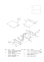
NOTE: • The mechanical parts with no reference number in the exploded views are not supplied. • Items marked "*" are not stocked since they are seldom required for routine service. Some delay should be anticipated when ordering these items. • -XX and -X mean standardized parts, so they may have some difference from the original one. SECTION 5 EXPLODED VIEWS • Color Indication of Appearance Parts Example : KNOB, BALANCE (WHITE) ... (RED) R R Parts Color Cabinet's Color • Accessories are given in the last of this parts list. • Abbreviation CND: Canadian model CDX-M800 The components identified by mark 0 or dotted line with mark 0 are critical for safety. Replace only with part number specified. Les composants identifiés par une marque 0 sont critiques pour la sécurité. Ne les remplacer que par une piéce portant le numéro spécifié. 5-1. CHASSIS SECTION 9 10 #1 8 #2 not supplied MG-393XC-121//K #1 7 34 6 A #1 5 1 A #2 not supplied 2 7 Ref. No. 1 1 2 3 4 5 6 7 Part No. Description Remark X-3382-819-1 PANEL (CD) SUB ASSY, SUB (US,CND) X-3382-825-1 PANEL (CD) SUB ASSY, SUB (AEP,UK,E) 1-783-268-11 CABLE, FLAT (FFC) 11P 1-687-950-11 SUB BOARD 3-232-857-01 SHEET (SUB PANEL), ELECTROSTATIC 3-248-826-01 COVER (FLEXIBLE) 3-230-516-01 SPRING (FLEXIBLE), TENSION 3-045-756-01 SCREW (PANEL) Ref. No. 8 8 9 10 #1 #2 Part No. Description Remark 1-776-207-72 1-776-527-71 3-223-913-11 3-248-858-01 7-685-790-09 CORD (WITH CONNECTOR) (POWER) (US,CND,E) CORD (WITH CONNECTOR) (ISO) (POWER) (AEP,UK) LABEL (OP CAUTION) (AEP,UK,E) BRACKET (CD) SCREW +PTT 2.6X4 (S) 7-685-792-09 SCREW +PTT 2.6X6 (S) 39
-
 1
1 -
2
-
3
-
4
-
5
-
6
-
7
-
8
-
9
-
10
-
11
-
12
-
13
-
14
-
15
-
16
-
17
-
18
-
19
-
20
-
21
-
22
-
23
-
24
-
25
-
26
-
27
-
28
-
29
-
30
-
31
-
32
-
33
-
 34
34 -
 35
35 -
 36
36 -
 37
37 -
 38
38 -
 39
39 -
 40
40 -
 41
41 -
 42
42 -
 43
43 -
 44
44 -
45
-
46
-
47
-
48
-
49
-
50
-
51
-
52
-
53
-
54
 |
 |
