Sony CDX-M800 Service Manual - Page 8
Disassembly, Front Panel Assy, Sub Panel Cd Sub Assy
 |
View all Sony CDX-M800 manuals
Add to My Manuals
Save this manual to your list of manuals |
Page 8 highlights
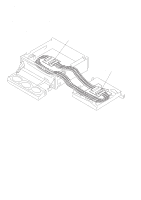
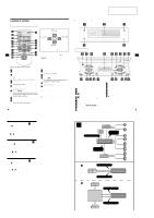
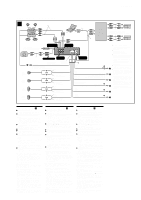
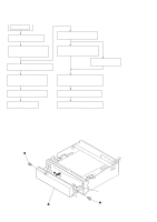
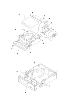
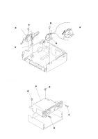
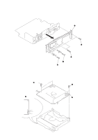
CDX-M800 SECTION 2 DISASSEMBLY Note : This set can be disassemble according to the following sequence. SET 2-1. FRONT PANEL ASSY (Page 8) 2-7. CHASSIS (T) SUB ASSY (Page 11) 2-2. CD MECHANISM BLOCK, FRONT PANEL ASSY (Page 9) 2-3. SUB PANEL (CD) SUB ASSY (Page 9) 2-8. LEVER SECTION, IN SELF SW BOARD (Page 12) 2-9. SERVO BOARD (Page 12) 2-4. MOTOR BLOCK ASSY, CAM (R) ASSY (Page 10) 2-10. SHAFT ROLLER ASSY, LOAD SW BOARD (Page 13) 2-5. MAIN BOARD (Page 10) 2-11. FLOATING BLOCK ASSY (Page 13) 2-6. HEAT SINK (Page 11) 2-12. OPTICAL PICK-UP BLOCK (Page 14) Note : Follow the disassembly procedure in the numerical order given. 2-1. FRONT PANEL ASSY 2 screw (panel) 3 4 front panel assy (Take care not to pull the flexible board excessively) 8 flexible board 1 screw (panel)
-
 1
1 -
2
-
 3
3 -
 4
4 -
 5
5 -
 6
6 -
 7
7 -
 8
8 -
 9
9 -
 10
10 -
 11
11 -
 12
12 -
 13
13 -
14
-
15
-
16
-
17
-
18
-
19
-
20
-
21
-
22
-
23
-
24
-
25
-
26
-
27
-
28
-
29
-
30
-
31
-
32
-
33
-
34
-
35
-
36
-
37
-
38
-
39
-
40
-
41
-
42
-
43
-
44
-
45
-
46
-
47
-
48
-
49
-
50
-
51
-
52
-
53
-
54
 |
 |
