Sony CDX-M800 Service Manual - Page 15
Phase Alignment, Arm (a-l) Assy, Cam (l), 2. Cam L
 |
View all Sony CDX-M800 manuals
Add to My Manuals
Save this manual to your list of manuals |
Page 15 highlights
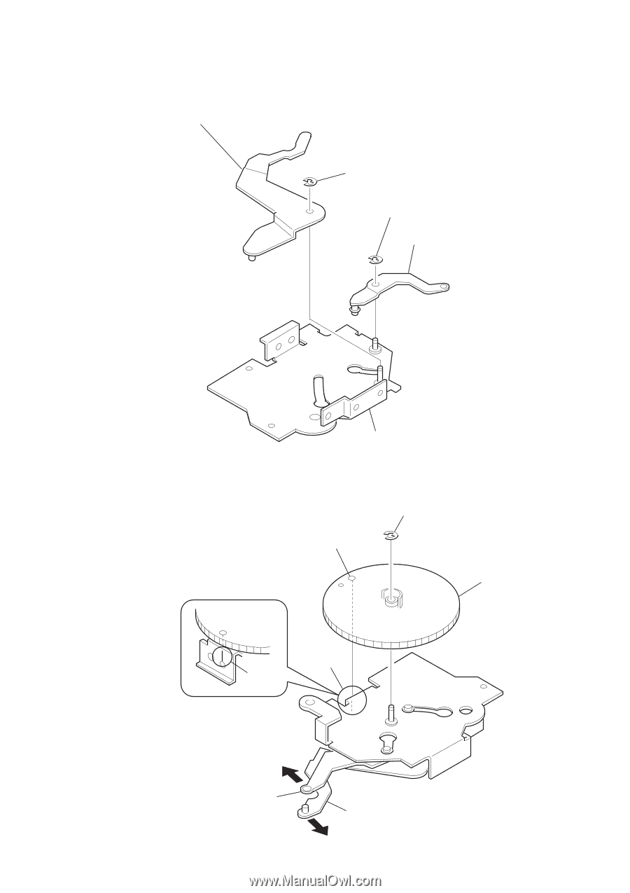
SECTION 3 PHASE ALIGNMENT 3-1. ARM (A-L) ASSY, ARM (B-L) ASSY 3 arm (A-L) assy 4 type-E stop ring 1.5 2 type-E stop ring 1.5 1 arm (B-L) assy CDX-M800 3-2. CAM (L) 1 Move the arm (B-L) assy in the direction of the arrow A and the arm (A-L) assy in the direction of the arrow B fully (full open state). 2 Align the hole (large) on the cam (L) with part C and install the cam. 4 Turn the cam (L) clockwise and counterclockwise to verify that both the arms are operated. bracket (L) assy hole (large) 3 type-E stop ring 1.5 cam (L) C line A arm (B-L) assy arm (A-L) assy B 15
-
 1
1 -
2
-
3
-
4
-
5
-
6
-
7
-
8
-
9
-
 10
10 -
 11
11 -
 12
12 -
 13
13 -
 14
14 -
 15
15 -
 16
16 -
 17
17 -
 18
18 -
 19
19 -
 20
20 -
21
-
22
-
23
-
24
-
25
-
26
-
27
-
28
-
29
-
30
-
31
-
32
-
33
-
34
-
35
-
36
-
37
-
38
-
39
-
40
-
41
-
42
-
43
-
44
-
45
-
46
-
47
-
48
-
49
-
50
-
51
-
52
-
53
-
54
 |
 |
15
CDX-M800
cam (L)
arm (A-L) assy
arm (B-L) assy
C
A
B
3
type-E stop ring 1.5
hole (large)
line
SECTION 3
PHASE ALIGNMENT
3-1. ARM (A-L) ASSY, ARM (B-L) ASSY
3-2. CAM (L)
1
Move the arm (B-L) assy in the direction of the
arrow
A
and the arm (A-L) assy in the direction of
the arrow
B
fully (full open state).
2
Align the hole (large) on the cam (L) with part
C
and
install the cam.
4
Turn the cam (L) clockwise and counterclockwise to
verify that both the arms are operated.
4
type-E stop ring 1.5
2
type-E stop ring 1.5
1
arm (B-L) assy
3
arm (A-L) assy
bracket (L) assy