Sony FWD-50PX2 User Manual - Page 11
Remote Commander RM-980 - power
 |
View all Sony FWD-50PX2 manuals
Add to My Manuals
Save this manual to your list of manuals |
Page 11 highlights
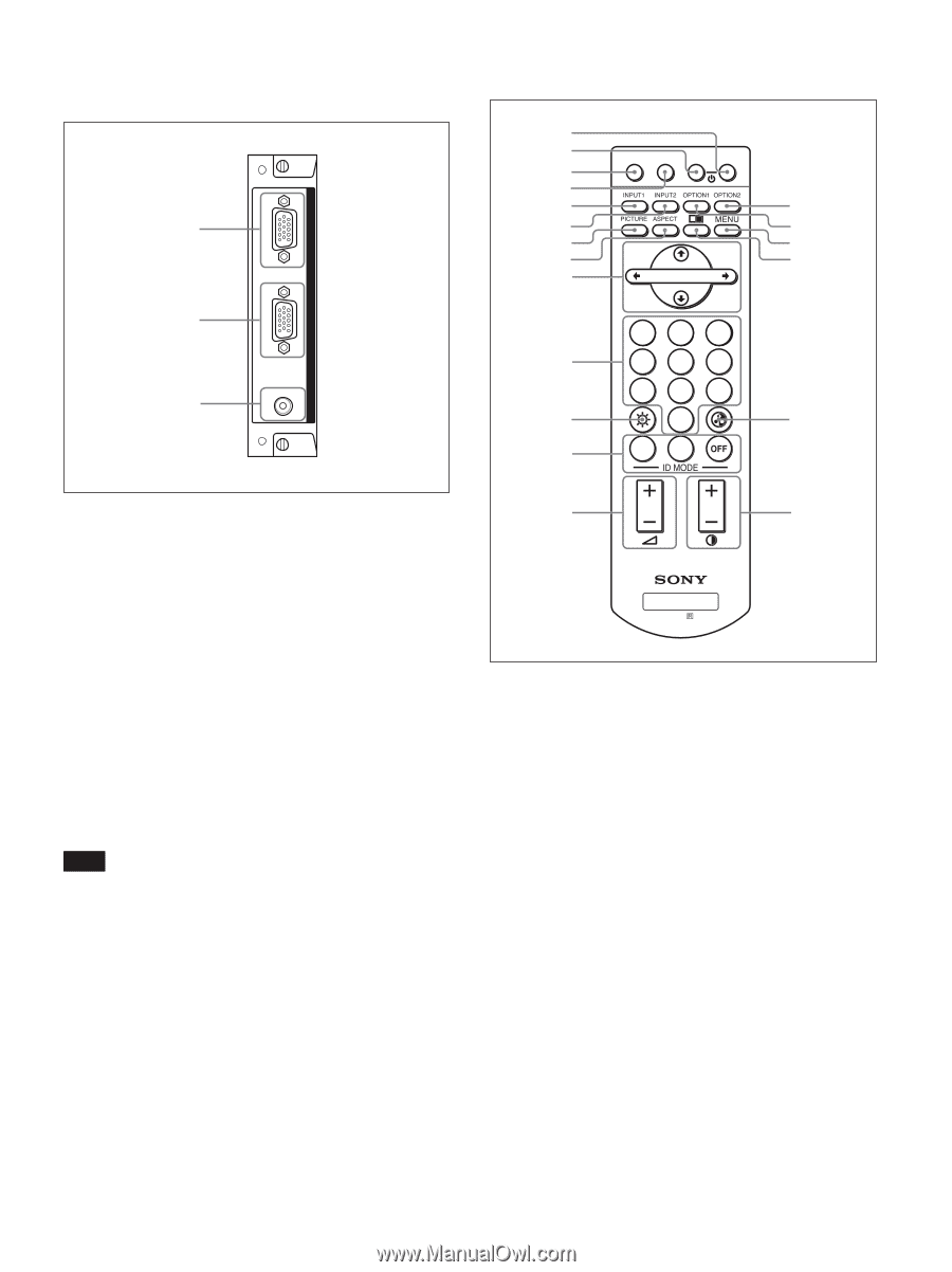
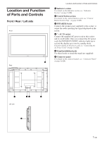
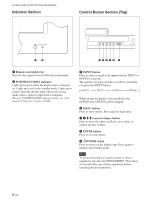
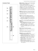
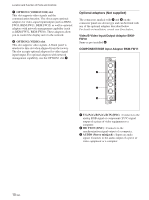
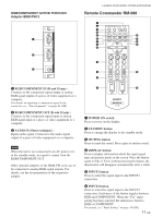
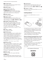
RGB/COMPONENT ACTIVE THROUGH Adaptor BKM-FW12 1 2 3 AUDIO IN OUT IN RGB/COMPONENT THROUGH Location and Function of Parts and Controls Remote Commander RM-980 1 2 MUTING DISPLAY STBY ON 3 4 5 qf 6 qg 7 qh 8 qj 9 ENTER 123 0 456 789 qa 0 qk qs ON SET 1 RGB/COMPONENT IN (D-sub 15-pin) : Connects to the component signal output or analog RGB signal output of a piece of video equipment or a computer. For details on inputting a component signal to the connector, see "Pin assignment" on page 49 (GB). 2 RGB/COMPONENT OUT (D-sub 15-pin) : Connects to the component signal input or analog RGB signal input of a piece of video equipment or a computer. 3 AUDIO IN (Stereo minijack) : Inputs audio signal. Connects to the audio signal output of a piece of video equipment or a computer. Note When the unit is not connected to an AC power or is in the standby mode, no signal is output from the RGB/COMPONENT OUT. Other optional adaptors of the BKM-FW series are to be connected to analog RGB signal outputs. For details, see the documentation of the respective adaptor. qd ql MONITOR RM-980 1 POWER ON switch Press to power on the display. 2 STANDBY button Press to change the display to the standby mode. 3 MUTING button Press to mute the sound. Press again to restore sound. 4 DISPLAY button Press to display information about the input signal type and picture mode on the screen. Press the button again to hide it. Even without pressing the button, the information will disappear automatically after a while. 5 INPUT1 button Press to select the signal input to the INPUT1 connectors. 6 INPUT2 button Press to select the signal input to the INPUT2 connectors. Each press of the button toggles between RGB and COMPONENT. When the "Fix" input setting has been selected, the selection is fixed to RGB or COMPONENT. For details, see "Input Setting" on page 19 (GB). 11 (GB)
-
 1
1 -
2
-
3
-
4
-
5
-
 6
6 -
 7
7 -
 8
8 -
 9
9 -
 10
10 -
 11
11 -
 12
12 -
 13
13 -
 14
14 -
 15
15 -
 16
16 -
17
-
18
-
19
-
20
-
21
-
22
-
23
-
24
-
25
-
26
-
27
-
28
-
29
-
30
-
31
-
32
-
33
-
34
-
35
-
36
-
37
-
38
-
39
-
40
-
41
-
42
-
43
-
44
-
45
-
46
-
47
-
48
-
49
-
50
 |
 |