Sony HDRC-4000 Operation Guide - Page 4
SR Live Metadata input/output, HDR Look function
 |
View all Sony HDRC-4000 manuals
Add to My Manuals
Save this manual to your list of manuals |
Page 4 highlights
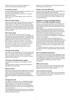
3G/HD-SDI Multi-Link and 12G/6G-SDI Single-Link conversion are supported using this function. Low-latency output All signal processing is performed within a single frame, and the output video is delayed by one frame. When the frame synchronizer function is on, the output is delayed by two frames. (When 4K is output as SQD signals, there is a further one frame delay.) Minimum delay setting When the system frequency is 59.94/50 and the input/output signal setting is 4K (2SI), enabling minimum delay mode causes a delay in 4K output of only a few lines (in HD signal terms). When the system frequency is 29.97/25/24/23.98 and an SQD signal is set for 4K input/output signal, the 4K output delay is one frame or higher (same as minimum delay mode not being enabled). HD×4 input mode You can use 4K INPUT connectors as four HD inputs. This is supported only when the input format is 1080/59.94P, 50P, 59.94i, 50i, 29.97PsF, 25PsF, 24PsF, or 23.98PsF on four channels, and all four inputs must be in the same format. The OETF setting of the outputs cannot be set individually. For HD×4 input, prioritize use of the CH-1 input and CH-3 input. If there is no input on CH-1, CH-2 to CH-4 cannot be used. If there is no input on CH-3, CH-4 cannot be used. One of the four systems among the 4K INPUT 1 to 4 connectors can be selected for output on the HD OUT connector. Through mode setting In through mode, SDI signals input on the 4K input connectors (BNC × 4) are output on the 4K output connectors (BNC × 4) with a 1-line delay (in HD signal terms). The 4K INPUT 1 connector signal is output as-is on the HD output. However, 720P input is not supported. 16-channel embedded audio support Audio signals (16-channel) can be embedded in the SDI signals. The audio signal with a delay matching the video signal is embedded in the output signal. Remote control Supports the remote control by Sony system camera products. Format setting, HDR/SDR setting, OETF setting, color space setting, image quality setting, file operation, and menu operation are supported from an RCP-3500/1500 series Remote Control Panel or an MSU-1000 series Master Setup Unit. Configuration file The settings of the SETUP menu and ADDITIONAL PAINT menu within the unit can be stored in up to five scene files each for channel A and channel B. The settings in the CONFIGURATION menu, SETUP menu, and ADDITIONAL PAINT menu can also be stored in up to 32 configuration files as an all-settings file. The exporting and importing of each file can be controlled from an RCP-3500/1500 series Remote Control Panel or an MSU1000 series Master Setup Unit. Furthermore, an all-settings file can be recalled from the I/O PORT connector (D-Sub 15-pin). Preserve and map ANC data Various conversions are supported while preserving ANC data (Ancillary Data) multiplexed with the SDI signal. VANC data (Vertical Ancillary Data) is used for mapping data from the input SDI signal to the output SDI signal. There are two modes that determine how the data is mapped (normal mode and field mode). Operation of camera with HyperGamma function as an HDR-compatible camera Cameras, such as the HDC1000 series and HDC2000 series, that feature the HyperGamma function can be operated as HDR-compatible cameras by selecting HyperGamma 4 as the gamma table. When HyperGamma 4 is selected as the gamma table, an image with a wider dynamic range than when using normal gamma is output. When this image is input to the unit and the input OETF is set to HyperGamma4, the image from the camera can be handled as an HDR signal, and it can be converted to an S-Log3 or HLG HDR signal or an SDR signal that uses normal gamma. However, since standard camera settings typically overenhance high-luminance contours using the detail function, it is recommended that the detail function Mix Ratio value on the camera be reduced or that the detail function be set to OFF. Even when the detail function on the camera is set to OFF, contours can still be enhanced by enabling the detail function of the unit. It is recommended that you adjust the iris and other controls so that the white level in the HyperGamma 4 image output is set to 74%. SR Live Metadata input/output When generating an SDR signal from an HDR signal, you can embed a group of required settings (HDR SDR Relation Table) in the VANC space of the SDI signal. This allows a receiving device to display the settings or to apply the group of settings to the HDR signal to SDR signal conversion settings automatically. HDR Look function HDR Look is a video characteristic that determines how the video signal captured by the camera is represented on the display. It can be set to Live, Mild, or Natural. Look conversion function When converting from HDR to HDR, the basic characteristics of the video (HDR Look and HDR Black Compression) can be converted at the input and output. 4
-
 1
1 -
 2
2 -
 3
3 -
 4
4 -
 5
5 -
 6
6 -
 7
7 -
 8
8 -
 9
9 -
 10
10 -
11
-
12
-
13
-
14
-
15
-
16
-
17
-
18
-
19
-
20
-
21
-
22
-
23
-
24
-
25
-
26
-
27
-
28
-
29
-
30
-
31
-
32
-
33
-
34
-
35
-
36
-
37
-
38
-
39
-
40
-
41
-
42
-
43
-
44
-
45
-
46
-
47
-
48
-
49
-
50
-
51
-
52
-
53
-
54
-
55
-
56
-
57
-
58
-
59
-
60
 |
 |
