Sony HDRC-4000 Operation Guide - Page 6
Name and Function of Parts, Front Panel
 |
View all Sony HDRC-4000 manuals
Add to My Manuals
Save this manual to your list of manuals |
Page 6 highlights
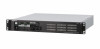
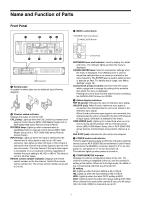
Name and Function of Parts Front Panel a b cd POWER CALL CALL RCP/MSU RCP/MSU INPUT CH A INPUT CH B CONFIGURATION 4K HD HDR 2020 A B IN 2SI HDR 2020 HDR 2020 4K OUT HD OUT MENU DISP CANCEL MENU ENTER REF IN UNLOCK COM ERROR FAN STOP MENU LOCK OFF ON NETWORK e f gh USB connector a Number plate A supplied number plate can be attached (see following diagram). b Channel status indicator Displays the status of channel A/B. CALL lamp: Lights up when the CALL button is pressed on an external control device (MSU-1000 Master Setup Unit or RCP-3500/1500 series Remote Control Panel). RCP/MSU lamp: Lights up when communication is established with an external control device (MSU-1000 Master Setup Unit or RCP-3500/1500 series Remote Control Panel). INPUT lamp: Lights up when HD input is selected for the channel and a video signal is input on an HD input connector. Also lights up when 4K input or HD×4 input is selected for the channel and a video signal is input on a 4K input connector. The lamp flashes if the input video signal is incomplete or is not received correctly, regardless of whether the input setting is 4K, HD, or HD×4. The lamp is not lit in all other cases. Remote control number indicator: Displays the remote control number set for the channel. Not lit if the remote control number is 0. The remote control number can be set to 0 to 96. c MENU control block DISP/MENU lever and indicator CANCEL/ENTER lever MENU DISP CANCEL MENU ENTER Control knob DISP/MENU lever and indicator: Used to display the status and menu. The indicator lights up when the menu is displayed. CANCEL/ENTER lever: Used to cancel/enter settings when the menu is displayed. The CANCEL lever is used to cancel the selected item or to move up one level in the menu hierarchy. The ENTER lever is used to select an item or execute an item. For details about usage, see "Menu Settings" (page 19). Control knob (rotary encoder): Used to move the cursor within a page and to change the setting of the selected item when the menu is displayed. Pushing the control knob has the same function as setting the CANCEL/ENTER lever to ENTER. d Status display indicators REF IN (green): Indicates the input of reference sync signal. UNLOCK (red): When lit and a reference sync signal is connected, this indicates that the unit is not locked to the reference sync signal. When lit and a reference sync signal is not connected, this indicates that the unit is not locked to the 4K or HD channel A input signal, whichever is selected in the menu. COM ERROR (red): Lights up for a fixed time when an error occurs during communication with an external control device (MSU-1000 Master Setup Unit or RCP-3500/1500 series Remote Control Panel) connected to channel A or B. FAN STOP (red): Indicates the internal fan has stopped. e POWER switch and indicator Turns the system power supply on/off to the unit and an external device (such as RCP-3500/1500 series Remote Control Panel) connected to the REMOTE connector. Switch to "?" to turn the power on, and switch to "a" to turn the power off. The indicator lights up when power is turned on. f CONFIGURATION indicator Displays the internal configuration status of the unit. The channel A setting is displayed at the top, and the channel B setting at the bottom. When set to through mode, the LEDs of the corresponding channels are all turned off. IN setting 4K: Lights up when the input setting is 4K or HD×4. HD: Lights up when the input setting is HD or HD×4. HDR: Lights up when the input OETF setting is HDR. 2020: Lights up when the input color space setting is BT.2020. When channel A is used as the channel B input, the IN lamps (4K, HD, HDR, 2020) for channel B are all off. 6
-
 1
1 -
 2
2 -
 3
3 -
 4
4 -
 5
5 -
 6
6 -
 7
7 -
 8
8 -
 9
9 -
 10
10 -
 11
11 -
 12
12 -
13
-
14
-
15
-
16
-
17
-
18
-
19
-
20
-
21
-
22
-
23
-
24
-
25
-
26
-
27
-
28
-
29
-
30
-
31
-
32
-
33
-
34
-
35
-
36
-
37
-
38
-
39
-
40
-
41
-
42
-
43
-
44
-
45
-
46
-
47
-
48
-
49
-
50
-
51
-
52
-
53
-
54
-
55
-
56
-
57
-
58
-
59
-
60
 |
 |
