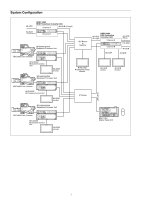
Sony HDRC-4000 Operation Guide - Page 7
Rear Panel, I/O PORT connector D-Sub 15-pin
 |
View all Sony HDRC-4000 manuals
Add to My Manuals
Save this manual to your list of manuals |
Page 7 highlights
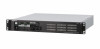
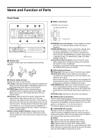
4K OUT setting 2SI: Lights up when the 4K output format is 2SI. HDR: Lights up when the 4K output or HD×4 output OETF setting is HDR. 2020: Lights up when the 4K output or HD×4 output color space setting is BT.2020. HD OUT setting HDR: Lights up when the HD output OETF setting is HDR. 2020: Lights up when the HD output color space setting is BT.2020. g NETWORK indicator Displays the network system connection status. On: Indicates that an external control device (MSU-1000 Master Setup Unit or RCP-3500/1500 series Remote Control Panel) is connected when the CNS MODE setting in is set to BRIDGE or MCS. Flashing: Indicates that an external control device (MSU1000 Master Setup Unit or RCP-3500/1500 series Remote Control Panel) is not connected successfully when the CNS MODE setting in is set to BRIDGE or MCS. Off: Indicates that the LAN cable is not connected or network system connection parameters have not been set when the CNS MODE setting in is set to BRIDGE or MCS. The indicator is always off when CNS MODE is set to LEGACY. For details, see "" (page 51). h Menu lock switch Disables operation of the menu control block on the front panel. Rear Panel a bc d e f I/O gh i a RCP/CNU CH-A, CH-B connectors (round type, 8-pin) Connect to an external control device (such as a MSU-1000 Master Setup Unit or RCP-3500/1500 series Remote Control Panel) or command network unit (such as a CNU-700) using a CCA-5 connection cable. Remote control signals are transmitted and received via this connector. It also supplies power when connected to an RCP-3500/1500 series Remote Control Panel. b REFERENCE IN/OUT (reference sync signal) connectors • IN connector (BNC type) (left) Input an external HD tri-level sync signal or SD reference sync signal (black burst signal). The type of reference sync signal is detected automatically and can be checked in the setup menu. • OUT connector (BNC type) (right) Outputs the reference sync signal input on the IN connector as-is (loop through). c (LAN) connector (RJ-45 8-pin) Connects to a LAN. Connect to a LAN hub (10BASE-T/ 100Base-TX) using a LAN cable (shielded type, category 5 or higher). CAUTION • For safety, do not connect the connector for peripheral device wiring that might have excessive voltage to this port. Follow the instructions for this port. • When you connect the LAN cable of the unit to peripheral device, use a shielded-type cable to prevent malfunction due to radiation noise. d HD INPUT CH-A, CH-B connectors Supports 3G/HD-SDI signal inputs (HD). e 4K INPUT CH-A, CH-B connectors Supports 12G/6G-SDI Single-Link or 3G/HD-SDI Multi-Link signal input (4K input). 3G/HD-SDI signals can also be input on four lines (HD input). For details about assignments to each signal output connector in the Single-Link interface and Multi-Link interface, see "Relationship between Connection Type and BNC Connector Assignment" (page 12). f - AC IN (AC power supply) connector Connect to the AC power supply using the specified power supply cord. The power supply cord can be attached to the unit using the optional plug holder. g I/O PORT connector (D-Sub 15-pin) Connect to an external control device. Can be used to recall an all-settings file or for switching the output of the CH-B MONITOR connector. h HD OUT CH-A, CH-B connectors 3G/HD-SDI signals (HD) are output from the MAIN connectors. HD output HD-SDI signals with superimposed setup menu or status are output from the MONITOR connectors. The monitor output of channel B or channel A can be output from the CH-B MONITOR connector. The monitor output channel can be selected using the menu of the unit or using the I/O PORT connector. i 4K OUT CH-A, CH-B connectors Outputs dual system 12G/6G-SDI Single-Link signals or 3G/ HD-SDI Multi-Link signals for each channel (4K output). 3G/HD-SDI signals can also be output on two 4-channel systems (HD output). For details about assignments to each signal output connector in the Single-Link interface and Multi-Link interface, see "Relationship between Connection Type and BNC Connector Assignment" (page 12). 7
-
 1
1 -
 2
2 -
 3
3 -
 4
4 -
 5
5 -
 6
6 -
 7
7 -
 8
8 -
 9
9 -
 10
10 -
 11
11 -
 12
12 -
13
-
14
-
15
-
16
-
17
-
18
-
19
-
20
-
21
-
22
-
23
-
24
-
25
-
26
-
27
-
28
-
29
-
30
-
31
-
32
-
33
-
34
-
35
-
36
-
37
-
38
-
39
-
40
-
41
-
42
-
43
-
44
-
45
-
46
-
47
-
48
-
49
-
50
-
51
-
52
-
53
-
54
-
55
-
56
-
57
-
58
-
59
-
60
 |
 |
