Sony HDW1800 Installation Manual - Page 20
Switch Settings on Connector Panel - hdw 1800 operations manual
 |
View all Sony HDW1800 manuals
Add to My Manuals
Save this manual to your list of manuals |
Page 20 highlights
VIDEO CONTROL: 9-pin (female) External view 5 1 Pin No. 1 2 3 4 5 6 7 8 9 96 Signal GND RM TX (_) RM RX (+) GND -- GND RM TX (+) RM RX (_) GND HDV IN (OPTION): 6-pin External view 1 2 3 4 5 6 Pin No. 1 2 3 4 5 6 Signal VP VG NTPB TPB NTPA TPA 1-9. Switch Settings on Connector Panel When the unit is installed, be sure to perform the following setup. Refer to the operation manual "Section 2 Location and Function of Parts" for setup. . Analog audio input level/600 Z termination switches . 75 Z termination switch of reference video input 1-14 (E) HDW-1800/D1800
-
 1
1 -
2
-
3
-
4
-
5
-
6
-
7
-
8
-
9
-
10
-
11
-
12
-
13
-
14
-
 15
15 -
 16
16 -
 17
17 -
 18
18 -
 19
19 -
 20
20 -
 21
21 -
 22
22 -
 23
23 -
 24
24 -
 25
25 -
26
-
27
-
28
-
29
-
30
-
31
-
32
-
33
-
34
-
35
-
36
-
37
-
38
 |
 |

1-14 (E)
HDW-1800/D1800
VIDEO CONTROL: 9-pin (female)
Pin No.
Signal
1
GND
2
RM TX (
_
)
3
RM RX (
+
)
4
GND
5
——
6
GND
7
RM TX (
+
)
8
RM RX (
_
)
9
GND
HDV IN (OPTION): 6-pin
Pin No.
Signal
1
VP
2
VG
3
NTPB
4
TPB
5
NTPA
6
TPA
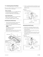
1-9.
Switch Settings on Connector Panel
When the unit is installed, be sure to perform the following
setup.
Refer to the operation manual
“
Section 2 Location and
Function of Parts
”
for setup.
.
Analog audio input level/600
Z
termination switches
.
75
Z
termination switch of reference video input
External view
1
5
9
6
External view
1
3
5
2
4
6