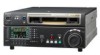
Sony HDW1800 Installation Manual - Page 5

Table of Contents - hdw 1800 manual

Page 5 highlights

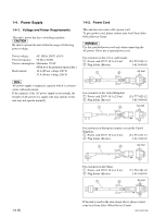
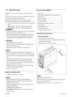
Table of Contents Manual Structure Purpose of this manual 2 (E) Related manuals 2 (E) 1. Installation 1-1. Installation Procedure 1-1 (E) 1-2. Supplied Accessories 1-1 (E) 1-3. Operating Conditions 1-1 (E) 1-4. Power Supply 1-2 (E) 1-4-1. Voltage and Power Requirements 1-2 (E) 1-4-2. Power Cord 1-2 (E) 1-5. Installation Space 1-3 (E) 1-6. Rack Mounting 1-4 (E) 1-7. Matching Connectors and Cables 1-9 (E) 1-8. Signal Inputs and Outputs 1-10 (E) 1-9. Switch Settings on Connector Panel 1-14 (E) 1-10. Switch Settings on Circuit Boards 1-15 (E) 1-10-1. APR-80 Board 1-15 (E) 1-11. Operation Mode Settings 1-17 (E) 1-11-1. Operation Procedure of Destination Selection Mode 1-17 (E) 1-12. Removing/Reattaching Lower Control Panel Unit 1-18 (E) 1-13. Switching Search Dial Mode 1-19 (E) 1-14. Reference System 1-20 (E) 1-15. Settings and Adjustment when External Equipment is Connected 1-21 (E) 1-15-1. Settings for Time Code 1-21 (E) 1-15-2. VTR Constant Values Settings of Editor ..... 1-21 (E) 1-15-3. System Phase Alignment 1-22 (E) 1-16. Removing/Reattaching Plug-in Board 1-22 (E) 1-17. Taking Out the Cassette in Tape Slacking 1-23 (E) Appendix A Setting Check Sheet HDW-1800/D1800 1 (E)

  • 1
  • 2
  • 3
  • 4
  • 5
  • 6
  • 7
  • 8
  • 9
  • 10
  • 11
  • 12
  • 13
  • 14
  • 15
  • 16
  • 17
  • 18
  • 19
  • 20
  • 21
  • 22
  • 23
  • 24
  • 25
  • 26
  • 27
  • 28
  • 29
  • 30
  • 31
  • 32
  • 33
  • 34
  • 35
  • 36
  • 37
  • 38

1 (E)
HDW-1800/D1800
Table of Contents
Manual Structure
Purpose of this manual
...........................................................
2 (E)
Related manuals
.....................................................................
2 (E)
1.
Installation
1-1.
Installation Procedure
..............................................
1-1 (E)
1-2.
Supplied Accessories
...............................................
1-1 (E)
1-3.
Operating Conditions
...............................................
1-1 (E)
1-4.
Power Supply
...........................................................
1-2 (E)
1-4-1.
Voltage and Power Requirements
..................
1-2 (E)
1-4-2.
Power Cord
.....................................................
1-2 (E)
1-5.
Installation Space
.....................................................
1-3 (E)
1-6.
Rack Mounting
........................................................
1-4 (E)
1-7.
Matching Connectors and Cables
............................
1-9 (E)
1-8.
Signal Inputs and Outputs
......................................
1-10 (E)
1-9.
Switch Settings on Connector Panel
......................
1-14 (E)
1-10.
Switch Settings on Circuit Boards
.........................
1-15 (E)
1-10-1.
APR-80 Board
..............................................
1-15 (E)
1-11.
Operation Mode Settings
.......................................
1-17 (E)
1-11-1.
Operation Procedure of Destination
Selection Mode
.............................................
1-17 (E)
1-12.
Removing/Reattaching Lower Control
Panel Unit
..............................................................
1-18 (E)
1-13.
Switching Search Dial Mode
.................................
1-19 (E)
1-14.
Reference System
..................................................
1-20 (E)
1-15.
Settings and Adjustment when External
Equipment is Connected
........................................
1-21 (E)
1-15-1.
Settings for Time Code
................................
1-21 (E)
1-15-2.
VTR Constant Values Settings of Editor
.....
1-21 (E)
1-15-3.
System Phase Alignment
..............................
1-22 (E)
1-16.
Removing/Reattaching Plug-in Board
...................
1-22 (E)
1-17.
Taking Out the Cassette in Tape Slacking
.............
1-23 (E)
Appendix A
Setting Check Sheet