Sony HDW1800 Installation Manual - Page 7
Installation - pdf
 |
View all Sony HDW1800 manuals
Add to My Manuals
Save this manual to your list of manuals |
Page 7 highlights
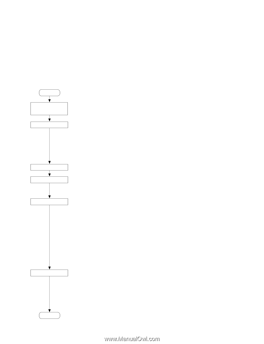
Section 1 Installation 1-1. Installation Procedure 1-2. Supplied Accessories Installation procedure of this unit is shown on the following flowchart. Refer to each section about detail of each flow. The operation manual is also required to do *-marked flow. Start Determination of installation place Unpacking 1-3. Operating Conditions 1-4. Power Supply 1-5. Installation Space n When the unit is transported, it is required to pack the unit into the specified new packing materials. Do not reuse the packing materials. Rack mounting 1-6. Rack Mounting *Connection 1-7. Matching Connectors and Cables 1-8. Signal Inputs and Outputs *Initial setup *Operation check 1-9. Switch Settings on Connector Panel 1-10. Switch Settings on Circuit Boards 1-11. Operation Mode Settings 1-12. Removing/Reattaching Lower Control Panel Unit 1-13. Switching Search Dial Mode 1-14. Reference System 1-15. Settings and Adjustment when External Equipment is Connected n If an error message appears on the time data display area, refer to the operation manual. (For more details, refer to the maintenance manual volume-1.) End . Screws for rack mounting (PSW 4 x 16 4 . Operation guide 1 . Operation manual CD-ROM (PDF 1 . Installation manual 1 1-3. Operating Conditions c Good air circulation is essential to prevent internal heat build-up. Place the unit in location with sufficient air circulation. Do not block the ventilation holes of the cabinet and the front and rear panels. Operating temperature: 5 dC to 40 dC Operating humidity: 25 % to 80 % (non-condensing) Storage temperature: _20 dC to 60 dC Locations to avoid: . Areas where the unit will be exposed to direct sunlight of any other strong lights. . Areas near heat sources. . Dusty areas or areas subject to vibration. . Areas with strong magnetic field. . Areas with much electrical noise. . Areas with much static electricity. . Areas that is impossible to find a specified room for installation. (Refer to "1-5. Installation Space".) . Areas windtight. Tilt allowance: Within 30d (Do not slant the front and rear of the unit more than 30d.) c Fix the unit securely to avoid drop when the unit is operat- ed at not-horizontal place. HDW-1800/D1800 1-1 (E)
-
 1
1 -
 2
2 -
 3
3 -
 4
4 -
 5
5 -
 6
6 -
 7
7 -
 8
8 -
 9
9 -
 10
10 -
 11
11 -
 12
12 -
13
-
14
-
15
-
16
-
17
-
18
-
19
-
20
-
21
-
22
-
23
-
24
-
25
-
26
-
27
-
28
-
29
-
30
-
31
-
32
-
33
-
34
-
35
-
36
-
37
-
38
 |
 |