Sony MDSJE320 Service Manual - Page 9
Disassembly
 |
UPC - 027242541344
View all Sony MDSJE320 manuals
Add to My Manuals
Save this manual to your list of manuals |
Page 9 highlights
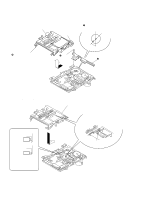
SECTION 3 DISASSEMBLY Note : Follow the disassembly procedure in the numerical order given. 3-1. CASE AND FRONT PANEL ASSEMBLY 1 Two screws (Case 3 TP 2) 4 Case 3 Screw (case 3 TP 2) 5 Ground terminal claw 2 Two screws (Case 3 TP 2) 9 Remove the front panel assembly releasing two claws. 8 Four screws (BVTP3×8) 3-2. BRACKET (T), (L) AND (R) 2 Bracket (T) claw 7 Three screws (BVTP3×8) 1 Four screws (BVTT2×3) 6 Flat type wire (CN303) 4 Screw (BVTT2×3) 3 Screw (BVTT2×3) 6 Two screws (BVTT2×3) 5 Bracket (joint) 7 Bracket (L) 9 Bracket (R) - 9 - 8 Two screws (BVTT2×3)
-
 1
1 -
2
-
3
-
 4
4 -
 5
5 -
 6
6 -
 7
7 -
 8
8 -
 9
9 -
 10
10 -
 11
11 -
 12
12 -
 13
13 -
 14
14 -
15
-
16
-
17
-
18
-
19
-
20
-
21
-
22
-
23
-
24
-
25
-
26
-
27
-
28
-
29
-
30
-
31
-
32
-
33
-
34
-
35
-
36
-
37
-
38
-
39
-
40
-
41
-
42
-
43
-
44
-
45
-
46
-
47
-
48
-
49
-
50
-
51
-
52
-
53
-
54
-
55
-
56
 |
 |

— 9 —
SECTION
3
DISASSEMBLY
Note :
Follow the disassembly procedure in the numerical order given.
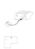
3-1. CASE AND FRONT PANEL ASSEMBLY
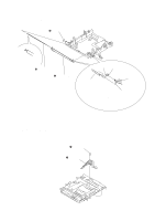
3-2. BRACKET (T), (L) AND (R)
4
Case
3
Screw
(case 3 TP 2)
2
Two screws
(Case 3 TP 2)
6
Flat type wire
(CN303)
claw
8
Four screws
(BVTP3
×
8)
9
Remove the front panel assembly
releasing two claws.
claw
1
Two screws
(Case 3 TP 2)
7
Three screws
(BVTP3
×
8)
5
Ground terminal
1
Four screws
(BVTT2
×
3)
4
Screw (BVTT2
×
3)
3
Screw (BVTT2
×
3)
5
Bracket (joint)
2
Bracket (T)
6
Two screws
(BVTT2
×
3)
7
Bracket (L)
9
Bracket (R)
8
Two screws
(BVTT2
×
3)