Stihl TS 500i STIHL Cutquik Instruction Manual - Page 28
Slacken the V-belt
 |
View all Stihl TS 500i STIHL Cutquik manuals
Add to My Manuals
Save this manual to your list of manuals |
Page 28 highlights
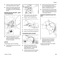
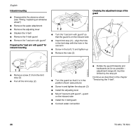
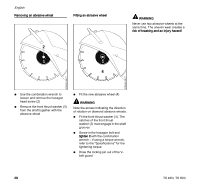
English Inboard mounting N Disassemble the abrasive wheel (see "Fitting / replacing an abrasive wheel") N Remove the water attachment N Remove the adjusting lever N Slacken the V-belt N Remove the V-belt guard N Remove the "cast arm with guard" Preparing the "cast arm with guard" for inboard mounting Checking the adjustment range of the guard 370BA081 KN 3 12 N Turn the "cast arm with guard" so that the guard is on the inboard side N Insert limit stop (2) - align the hole in the limit stop with the hole in the cast arm N Screw in the bolt (1) and tighten up N Remove the nuts (3) A 370BA080 KN 12 N Remove screw (1) from the limit stop (2) N Pull off the limit stop (2) 3 N Turn the guard so that it is in the position shown (see picture) N Screw in and tighten the stop pin (3) N Install the adjusting lever N Mount "cast arm with guard" - guard on the inboard side N Install the V-belt guard N Connect water connection 370BA082 KN N Rotate the guard forwards and backwards as far as possible - adjustment range (A) must be limited by the stop pin Continue as described in the chapter "Tensioning the V-belt". 370BA083 KN 26 TS 480i, TS 500i
-
 1
1 -
2
-
3
-
4
-
5
-
6
-
7
-
8
-
9
-
10
-
11
-
12
-
13
-
14
-
15
-
16
-
17
-
18
-
19
-
20
-
21
-
22
-
 23
23 -
 24
24 -
 25
25 -
 26
26 -
 27
27 -
 28
28 -
 29
29 -
 30
30 -
 31
31 -
 32
32 -
 33
33 -
34
-
35
-
36
-
37
-
38
-
39
-
40
-
41
-
42
-
43
-
44
-
45
-
46
-
47
-
48
-
49
-
50
-
51
-
52
-
53
-
54
-
55
-
56
-
57
-
58
-
59
-
60
-
61
-
62
-
63
-
64
-
65
-
66
-
67
-
68
-
69
-
70
-
71
-
72
-
73
-
74
-
75
-
76
-
77
-
78
-
79
-
80
-
81
-
82
-
83
-
84
-
85
-
86
-
87
-
88
-
89
-
90
-
91
-
92
-
93
-
94
-
95
-
96
-
97
-
98
-
99
-
100
-
101
-
102
-
103
-
104
 |
 |
