TP-Link N900 TL-WDN4200 V1 User Guide 1910010869 - Page 24
PIN method, 3.2.2.1. Enter the PIN from your Router or AP device, TL-WDN4200
 |
View all TP-Link N900 manuals
Add to My Manuals
Save this manual to your list of manuals |
Page 24 highlights
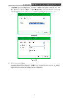
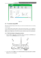
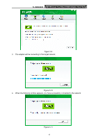
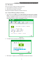
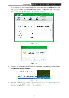
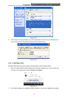
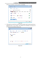
TL-WDN4200 N900 Wireless Dual Band USB Adapter User Guide 3.2.2 PIN method There are two ways to configure the WPS by PIN method: 1) Enter the PIN from your Router or AP device. 2) Enter a PIN into your Router or AP device. Following are the detailed configuration procedures of each way. 3.2.2.1. Enter the PIN from your Router or AP device 1. Open TWCU and click WPS tab. Select Enter the PIN of my access point or wireless Router. In the empty field beside PIN, enter the PIN labeled on the bottom of the Router (here takes 13492564 for example). If you have generated a new PIN code for your Router, please enter the new one instead. Click Connect to continue. Figure 3-12 2. The adapter will be connecting to the target network. Figure 3-13 3. When Figure 3-11 appears, you have successfully connected to the network. 16
-
 1
1 -
2
-
3
-
4
-
5
-
6
-
7
-
8
-
9
-
10
-
11
-
12
-
13
-
14
-
15
-
16
-
17
-
18
-
 19
19 -
 20
20 -
 21
21 -
 22
22 -
 23
23 -
 24
24 -
 25
25 -
 26
26 -
 27
27 -
 28
28 -
 29
29 -
30
-
31
-
32
-
33
-
34
-
35
-
36
-
37
-
38
-
39
-
40
-
41
-
42
-
43
-
44
-
45
-
46
-
47
-
48
-
49
-
50
-
51
-
52
-
53
-
54
 |
 |