Toshiba Portege M750-S7202 Portege M750 Series User Guide - Page 56
If no memory slot is available, you must remove a module by, performing steps
 |
View all Toshiba Portege M750-S7202 manuals
Add to My Manuals
Save this manual to your list of manuals |
Page 56 highlights
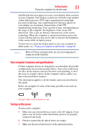
56 Getting Started Adding memory (optional) NOTE If no memory slot is available, you must remove a module by performing steps 2-3 of "Removing a memory module" on page 58. 11 Pick up the memory module by its sides, avoiding any contact with its connector. Position the module toward the socket, aligning the connector's notch with the matching key in the socket. notch latch connector latch key (Sample Illustration) Aligning the memory module with the socket 12 Firmly press the memory module into the memory slot's socket at approximately a 30-degree angle (to the horizontal surface of the computer). (Sample Illustration) Inserting the memory module into the socket
-
 1
1 -
2
-
3
-
4
-
5
-
6
-
7
-
8
-
9
-
10
-
11
-
12
-
13
-
14
-
15
-
16
-
17
-
18
-
19
-
20
-
21
-
22
-
23
-
24
-
25
-
26
-
27
-
28
-
29
-
30
-
31
-
32
-
33
-
34
-
35
-
36
-
37
-
38
-
39
-
40
-
41
-
42
-
43
-
44
-
45
-
46
-
47
-
48
-
49
-
50
-
 51
51 -
 52
52 -
 53
53 -
 54
54 -
 55
55 -
 56
56 -
 57
57 -
 58
58 -
 59
59 -
 60
60 -
 61
61 -
62
-
63
-
64
-
65
-
66
-
67
-
68
-
69
-
70
-
71
-
72
-
73
-
74
-
75
-
76
-
77
-
78
-
79
-
80
-
81
-
82
-
83
-
84
-
85
-
86
-
87
-
88
-
89
-
90
-
91
-
92
-
93
-
94
-
95
-
96
-
97
-
98
-
99
-
100
-
101
-
102
-
103
-
104
-
105
-
106
-
107
-
108
-
109
-
110
-
111
-
112
-
113
-
114
-
115
-
116
-
117
-
118
-
119
-
120
-
121
-
122
-
123
-
124
-
125
-
126
-
127
-
128
-
129
-
130
-
131
-
132
-
133
-
134
-
135
-
136
-
137
-
138
-
139
-
140
-
141
-
142
-
143
-
144
-
145
-
146
-
147
-
148
-
149
-
150
-
151
-
152
-
153
-
154
-
155
-
156
-
157
-
158
-
159
-
160
-
161
-
162
-
163
-
164
-
165
-
166
-
167
-
168
-
169
-
170
-
171
-
172
-
173
-
174
-
175
-
176
-
177
-
178
-
179
-
180
-
181
-
182
-
183
-
184
-
185
-
186
-
187
-
188
-
189
-
190
-
191
-
192
-
193
-
194
-
195
-
196
-
197
-
198
-
199
-
200
-
201
-
202
-
203
-
204
-
205
-
206
-
207
-
208
-
209
-
210
-
211
-
212
-
213
-
214
-
215
-
216
-
217
-
218
-
219
-
220
-
221
-
222
-
223
-
224
-
225
-
226
-
227
-
228
-
229
-
230
-
231
-
232
-
233
-
234
-
235
-
236
-
237
-
238
-
239
-
240
-
241
-
242
-
243
-
244
-
245
-
246
-
247
-
248
-
249
-
250
-
251
-
252
-
253
-
254
-
255
-
256
-
257
-
258
-
259
-
260
-
261
-
262
-
263
-
264
-
265
 |
 |
56
Getting Started
Adding memory (optional)
If no memory slot is available, you must remove a module by
performing steps
2
-
3
of
“Removing a memory module” on page 58
.
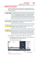
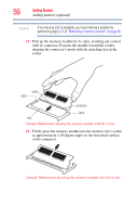
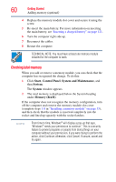
11
Pick up the memory module by its sides, avoiding any contact
with its connector. Position the module toward the socket,
aligning the connector’s notch with the matching key in the
socket.
(Sample Illustration) Aligning the memory module with the socket
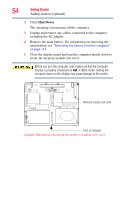
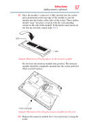
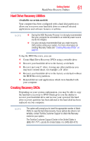
12
Firmly press the memory module into the memory slot’s socket
at approximately a 30-degree angle (to the horizontal surface
of the computer).
(Sample Illustration) Inserting the memory module into the socket
NOTE
latch
latch
key
notch
connector