Toshiba Tecra A3-S711 Maintenance Manual - Page 147
Installing the USB Board, Removing the System Board, Replacement Procedures,
 |
View all Toshiba Tecra A3-S711 manuals
Add to My Manuals
Save this manual to your list of manuals |
Page 147 highlights
4 Replacement Procedures Installing the USB Board Follow the step below to install the USB board. 1. Connect the USB cable to the connector on motherboard. Removing the System Board To remove the system board, first remove the LCD display assembly and the top cover, then follow the steps below: 1. Remove two 4.75 x 9.6 NI hexagonal screws securing the system board to the printer port. Figure 4-31 Removing the system board 2. Remove two 4.75 x 9.6 NI hexagonal screws securing the system board to the CRT port. 3. Remove three screws securing the Fan, and then detach the Fan from its connector. 4. Remove the system board. Tecra A3/S2 Series Maintenance Manual 4-35
-
 1
1 -
2
-
3
-
4
-
5
-
6
-
7
-
8
-
9
-
10
-
11
-
12
-
13
-
14
-
15
-
16
-
17
-
18
-
19
-
20
-
21
-
22
-
23
-
24
-
25
-
26
-
27
-
28
-
29
-
30
-
31
-
32
-
33
-
34
-
35
-
36
-
37
-
38
-
39
-
40
-
41
-
42
-
43
-
44
-
45
-
46
-
47
-
48
-
49
-
50
-
51
-
52
-
53
-
54
-
55
-
56
-
57
-
58
-
59
-
60
-
61
-
62
-
63
-
64
-
65
-
66
-
67
-
68
-
69
-
70
-
71
-
72
-
73
-
74
-
75
-
76
-
77
-
78
-
79
-
80
-
81
-
82
-
83
-
84
-
85
-
86
-
87
-
88
-
89
-
90
-
91
-
92
-
93
-
94
-
95
-
96
-
97
-
98
-
99
-
100
-
101
-
102
-
103
-
104
-
105
-
106
-
107
-
108
-
109
-
110
-
111
-
112
-
113
-
114
-
115
-
116
-
117
-
118
-
119
-
120
-
121
-
122
-
123
-
124
-
125
-
126
-
127
-
128
-
129
-
130
-
131
-
132
-
133
-
134
-
135
-
136
-
137
-
138
-
139
-
140
-
141
-
 142
142 -
 143
143 -
 144
144 -
 145
145 -
 146
146 -
 147
147 -
 148
148 -
 149
149 -
 150
150 -
 151
151 -
 152
152 -
153
-
154
-
155
-
156
-
157
-
158
-
159
-
160
-
161
-
162
-
163
-
164
-
165
-
166
-
167
-
168
-
169
-
170
-
171
-
172
-
173
-
174
-
175
-
176
-
177
-
178
-
179
-
180
-
181
-
182
-
183
-
184
-
185
-
186
-
187
-
188
-
189
-
190
-
191
-
192
-
193
-
194
-
195
-
196
-
197
-
198
-
199
-
200
-
201
-
202
-
203
-
204
-
205
-
206
-
207
-
208
 |
 |

4
Replacement Procedures
Tecra A3/S2 Series Maintenance Manual
4-35
Installing the USB Board
Follow the step below to install the USB board.
1.
Connect the USB cable to the connector on motherboard.
Removing the System Board
To remove the system board, first remove the LCD display assembly and the top cover, then follow the
steps below:
1.
Remove two 4.75 x 9.6 NI hexagonal screws securing the system board to the printer port.
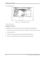
Figure 4-31
Removing the system board
2.
Remove two 4.75 x 9.6 NI hexagonal screws securing the system board to the CRT port.
3.
Remove three screws securing the Fan, and then detach the Fan from its connector.
4.
Remove the system board.