Toshiba Tecra A3-S711 Maintenance Manual - Page 45
Procedure 3, Power supply connection check, adaptor, System, board, Battery, AC adaptor cord
 |
View all Toshiba Tecra A3-S711 manuals
Add to My Manuals
Save this manual to your list of manuals |
Page 45 highlights
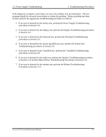
2 Troubleshooting Procedures 2.3 Power Supply Troubleshooting Procedure 3 Power supply connection check The power supply wiring diagram is shown below: AC power cord AC adaptor AC adaptor cord System board Battery Any of the connectors may be disconnected. Perform Check 1. Check 1 Disconnect the AC power cord from wall outlet. Check the power cable for breaks. If the power cord is damaged, connect a new AC power cord. If there is no damage, go to Check 2. Check 2 Make sure the AC adaptor cord and AC power cord are firmly plugged into the DCIN socket, AC adaptor inlet and wall outlet. If these cables are connected correctly, go to Check 3. Check 3 Make sure that the DC-IN input port socket is firmly secured to the system board of the computer. ? If the DC-IN input socket is loose, go to Procedure 5. ? If it is not loose, go to Check 4. Check 4 Use a multi- meter to make sure that the AC adaptor output voltage is close to 15V. If the output is several percent lower than 15V, go to Check 5. If the output is close to 15 V, go to Check 6. Check 5 Connect a new AC adaptor or AC power cord. ? If the DC-IN LED does not light, go to Procedure 4. ? If the battery LED does not light, go to Check 6. Check 6 Make sure the battery pack is installed in the computer correctly. If the battery is properly installed and the battery LED still does not light, go to Procedure 4. 2-10 Tecra A3/S2 Series Maintenance Manual
-
 1
1 -
2
-
3
-
4
-
5
-
6
-
7
-
8
-
9
-
10
-
11
-
12
-
13
-
14
-
15
-
16
-
17
-
18
-
19
-
20
-
21
-
22
-
23
-
24
-
25
-
26
-
27
-
28
-
29
-
30
-
31
-
32
-
33
-
34
-
35
-
36
-
37
-
38
-
39
-
 40
40 -
 41
41 -
 42
42 -
 43
43 -
 44
44 -
 45
45 -
 46
46 -
 47
47 -
 48
48 -
 49
49 -
 50
50 -
51
-
52
-
53
-
54
-
55
-
56
-
57
-
58
-
59
-
60
-
61
-
62
-
63
-
64
-
65
-
66
-
67
-
68
-
69
-
70
-
71
-
72
-
73
-
74
-
75
-
76
-
77
-
78
-
79
-
80
-
81
-
82
-
83
-
84
-
85
-
86
-
87
-
88
-
89
-
90
-
91
-
92
-
93
-
94
-
95
-
96
-
97
-
98
-
99
-
100
-
101
-
102
-
103
-
104
-
105
-
106
-
107
-
108
-
109
-
110
-
111
-
112
-
113
-
114
-
115
-
116
-
117
-
118
-
119
-
120
-
121
-
122
-
123
-
124
-
125
-
126
-
127
-
128
-
129
-
130
-
131
-
132
-
133
-
134
-
135
-
136
-
137
-
138
-
139
-
140
-
141
-
142
-
143
-
144
-
145
-
146
-
147
-
148
-
149
-
150
-
151
-
152
-
153
-
154
-
155
-
156
-
157
-
158
-
159
-
160
-
161
-
162
-
163
-
164
-
165
-
166
-
167
-
168
-
169
-
170
-
171
-
172
-
173
-
174
-
175
-
176
-
177
-
178
-
179
-
180
-
181
-
182
-
183
-
184
-
185
-
186
-
187
-
188
-
189
-
190
-
191
-
192
-
193
-
194
-
195
-
196
-
197
-
198
-
199
-
200
-
201
-
202
-
203
-
204
-
205
-
206
-
207
-
208
 |
 |
