Toshiba Tecra A3-S711 Maintenance Manual - Page 155
Installing the LCD Module, If the LCD module malfunctions, remove the LCD cable and LCD bracket. Then
 |
View all Toshiba Tecra A3-S711 manuals
Add to My Manuals
Save this manual to your list of manuals |
Page 155 highlights
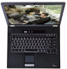
4 Replacement Procedures 3. Remove eight M2x3 screws securing LCD module bracket to the LCD module. Figure 4-38 Removing the LCD module-2 1. Remove the LCD module. NOTE: If the LCD module malfunctions, remove the LCD cable and LCD bracket. Then replace the whole LCD module unit. Installing the LCD Module To install the LCD module, follow the steps below and refer to the figures in the preceding section. 1. Set the LCD module in the display assembly. 2. Secure the LCD module bracket to the LCD module with eight M2x3 screws. 3. Connect the LCD cable to the FL inverter board. 4. Secure the LCD module bracket to the LCD module with two M2.5x5 screws. Tecra A3/S2 Series Maintenance Manual 4-43
-
 1
1 -
2
-
3
-
4
-
5
-
6
-
7
-
8
-
9
-
10
-
11
-
12
-
13
-
14
-
15
-
16
-
17
-
18
-
19
-
20
-
21
-
22
-
23
-
24
-
25
-
26
-
27
-
28
-
29
-
30
-
31
-
32
-
33
-
34
-
35
-
36
-
37
-
38
-
39
-
40
-
41
-
42
-
43
-
44
-
45
-
46
-
47
-
48
-
49
-
50
-
51
-
52
-
53
-
54
-
55
-
56
-
57
-
58
-
59
-
60
-
61
-
62
-
63
-
64
-
65
-
66
-
67
-
68
-
69
-
70
-
71
-
72
-
73
-
74
-
75
-
76
-
77
-
78
-
79
-
80
-
81
-
82
-
83
-
84
-
85
-
86
-
87
-
88
-
89
-
90
-
91
-
92
-
93
-
94
-
95
-
96
-
97
-
98
-
99
-
100
-
101
-
102
-
103
-
104
-
105
-
106
-
107
-
108
-
109
-
110
-
111
-
112
-
113
-
114
-
115
-
116
-
117
-
118
-
119
-
120
-
121
-
122
-
123
-
124
-
125
-
126
-
127
-
128
-
129
-
130
-
131
-
132
-
133
-
134
-
135
-
136
-
137
-
138
-
139
-
140
-
141
-
142
-
143
-
144
-
145
-
146
-
147
-
148
-
149
-
 150
150 -
 151
151 -
 152
152 -
 153
153 -
 154
154 -
 155
155 -
 156
156 -
 157
157 -
 158
158 -
 159
159 -
 160
160 -
161
-
162
-
163
-
164
-
165
-
166
-
167
-
168
-
169
-
170
-
171
-
172
-
173
-
174
-
175
-
176
-
177
-
178
-
179
-
180
-
181
-
182
-
183
-
184
-
185
-
186
-
187
-
188
-
189
-
190
-
191
-
192
-
193
-
194
-
195
-
196
-
197
-
198
-
199
-
200
-
201
-
202
-
203
-
204
-
205
-
206
-
207
-
208
 |
 |

4
Replacement Procedures
Tecra A3/S2 Series Maintenance Manual
4-43
3.
Remove eight M2x3 screws securing LCD module bracket to the LCD module.
Figure 4-38
Removing the LCD module-2
1.
Remove the LCD module.
NOTE
: If the LCD module malfunctions, remove the LCD cable and LCD bracket. Then
replace the whole LCD module unit.
Installing the LCD Module
To install the LCD module, follow the steps below and refer to the figures in the preceding section.
1.
Set the LCD module in the display assembly.
2.
Secure the LCD module bracket to the LCD module with eight M2x3 screws.
3.
Connect the LCD cable to the FL inverter board.
4.
Secure the LCD module bracket to the LCD module with two M2.5x5 screws.