Tripp Lite SMART1000RT1U Owners Manual for SmartPro Line-Interactive Single-Ph - Page 13
-Segment Display
 |
View all Tripp Lite SMART1000RT1U manuals
Add to My Manuals
Save this manual to your list of manuals |
Page 13 highlights
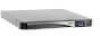
2 Features 2.2.4 7-Segment Display Column A Column B 7-Segment Display Note: Read the word shown in Column A together with that in Column B to interpret the display meaning. Icon IN OUT SET TEST BATT LOAD Description IN & V When the IN and V illuminate together, the input voltage is displayed. IN & Hz When IN and Hz illuminate together, the input frequency is displayed. OUT & V When OUT and V illuminate together, the output voltage is displayed. OUT & Hz When OUT and Hz illuminate together, the output frequency is displayed. When SET illuminates, the UPS is in setup mode. You can set up the following items via the LCD. For how to enter setup mode, refer to section 5.5 Setup Mode. 1. Audible alarm 2. Inverter voltage 3. Input sensitivity When TEST flashes, the UPS is performing a battery test. BATT & % When BATT and % illuminate together, the remaining battery capacity is displayed. BATT & V When BATT and V illuminate together, the battery voltage is displayed. RUN TIME & MIN When RUN TIME and MIN illuminate together, battery runtime under the current load is displayed. LOAD & % When LOAD and % illuminate together, the total load capacity is displayed. LOAD & KVA When LOAD and KVA illuminate together, the total kVA load is displayed. LOAD & KW When LOAD and KW illuminate together, the total kW load is displayed. 13
-
 1
1 -
2
-
3
-
4
-
5
-
6
-
7
-
 8
8 -
 9
9 -
 10
10 -
 11
11 -
 12
12 -
 13
13 -
 14
14 -
 15
15 -
 16
16 -
 17
17 -
 18
18 -
19
-
20
-
21
-
22
-
23
-
24
-
25
-
26
-
27
-
28
-
29
-
30
-
31
-
32
-
33
-
34
-
35
-
36
-
37
-
38
-
39
-
40
-
41
-
42
-
43
-
44
-
45
-
46
-
47
-
48
-
49
-
50
-
51
-
52
-
53
-
54
-
55
-
56
-
57
-
58
-
59
-
60
-
61
-
62
-
63
-
64
-
65
-
66
-
67
-
68
-
69
-
70
-
71
-
72
-
73
-
74
-
75
-
76
-
77
-
78
-
79
-
80
-
81
-
82
-
83
-
84
-
85
-
86
-
87
-
88
-
89
-
90
-
91
-
92
 |
 |
