Weider Pro 9600 English Manual - Page 19
Seat Assembly
 |
View all Weider Pro 9600 manuals
Add to My Manuals
Save this manual to your list of manuals |
Page 19 highlights
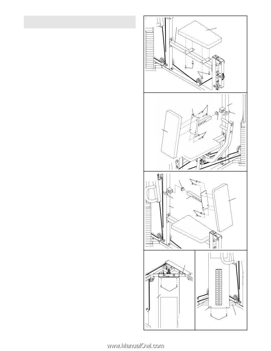
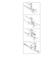
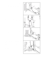
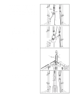
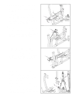
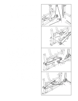
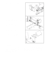
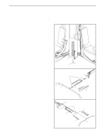
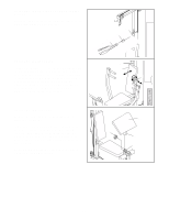
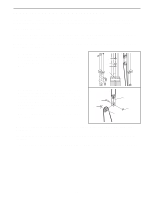
SEAT ASSEMBLY 51 51. Locate and open the parts bag labeled "SEAT ASSEMBLY." Attach a Seat (13) to the brackets on the Butterfly Seat Frame (14) using four 1/4" x 3/4" Bolts (49). Repeat this step with the other Seat (not shown) and the Press Seat Frame (not shown). 14 13 49 52. Press a 1 1/2" Square Inner Cap (35) into the end of the Press Backrest Frame (44). Attach a Backrest (12) to the Press Backrest Frame with four 1/4" x 3/4" Bolts (49). Pull out the Adjustment Knob (5) on the Press Upright (2) as far as it can go. Slide the Press Backrest Frame (44) into the Press Upright and snap the Adjustment Knob into a hole in the Press Backrest Frame. Turn the Adjustment Knob clockwise until tight. 52 12 49 2 44 5 35 49 53. Press a 1 1/2" Square Inner Cap (35) into the end 53 of the Butterfly Backrest Frame (70). Attach the other Backrest (12) to the Butterfly Backrest Frame with four 1/4" x 3/4" Bolts (49). 35 49 Pull out the Adjustment Knob (5) on the Butterfly 5 70 12 Upright (1) as far as it can go. Slide the Butterfly Backrest Frame (70) into the Butterfly Upright and 1 49 snap the Adjustment Knob into a hole in the Butterfly Backrest Frame. Turn the Adjustment Knob clockwise until tight. 54. See drawing A. Attach the Shroud (34) to the 54 A Press Top Frame (9) with two #8 x 1/2" Screws B (45). 9 See drawing B. Attach the Shroud (34) to the Press Base (6) with two #8 x 1/2" Screws (45). 45 34 34 6 45 19
-
 1
1 -
2
-
3
-
4
-
5
-
6
-
7
-
8
-
9
-
10
-
11
-
12
-
13
-
 14
14 -
 15
15 -
 16
16 -
 17
17 -
 18
18 -
 19
19 -
 20
20 -
 21
21 -
 22
22 -
 23
23 -
 24
24 -
25
-
26
-
27
-
28
-
29
-
30
-
31
-
32
-
33
-
34
-
35
 |
 |