Weider Wedier Pro 9635 Canadian English Manual - Page 13
Locate the Low Cable 23.
 |
View all Weider Wedier Pro 9635 manuals
Add to My Manuals
Save this manual to your list of manuals |
Page 13 highlights
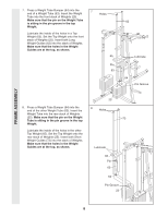
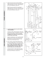
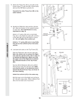
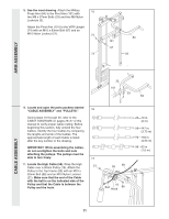
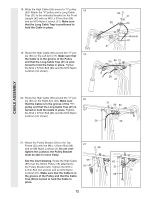
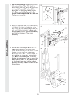
CABLE ASSEMBLY 22. See the inset drawing. Route the High Cable (58) under a 90mm Pulley (15). Attach the Pulley and a Cable Trap (66) to the upper hole in a Long "U"-bracket (57) with an M10 x 47mm Bolt (12) and an M10 Nylon Locknut (21). Make sure that the Cable is in the groove of the Pulley and that the Cable and Pulley move smoothly. 22 66 21 57 58 15 12 23. Wrap the High Cable (58) over a 90mm Pulley 23 (15). Attach the Pulley to the bracket on the Top Frame (55) with an M10 x 47mm Bolt (12) and an M10 Nylon Locknut (21). Make sure that the Cable is in the groove of the Pulley and that the Cable and Pulley move smoothly. 57 58 Bracket 15 58 12 15 55 21 24. Locate the Low Cable (23). Route the Low Cable under the 90mm Reinforced Pulley 24 (106). Attach the Pulley and the 16mm x 14mm Spacer (7) to the lower hole in the Press Frame (17) with an M10 x 92mm Bolt (88), an M10 Washer (9), and an M10 Nylon Locknut (21). Make sure that the parts are assem- bled in the order shown, that the end of the Cable with the ball is on the indicated side of the Press Frame, and that the Cable is between the Pulley and the crossbar on the Press Frame. Crossbar 9 17 88 106 7 23 21 Ball 13
-
 1
1 -
2
-
3
-
4
-
5
-
6
-
7
-
 8
8 -
 9
9 -
 10
10 -
 11
11 -
 12
12 -
 13
13 -
 14
14 -
 15
15 -
 16
16 -
 17
17 -
 18
18 -
19
-
20
-
21
-
22
-
23
-
24
-
25
-
26
-
27
-
28
-
29
-
30
-
31
-
32
-
33
-
34
 |
 |
