Weider Wedier Pro 9635 Canadian English Manual - Page 9
Frame Assembly, Arm Assembly
 |
View all Weider Wedier Pro 9635 manuals
Add to My Manuals
Save this manual to your list of manuals |
Page 9 highlights
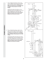
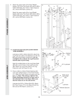
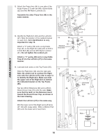
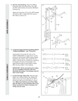
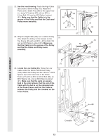
9. Attach the upper ends of the Short Weight Guides (73) to the Top Frame (55) with an M8 x 150mm Bolt (60), two 13mm x 19mm Spacers (61), and an M8 Nylon Locknut (3). Attach the upper ends of the Long Weight Guides (62) to the Top Frame (55) with an M8 x 150mm Bolt (60), two 13mm x 19mm Spacers (61), and an M8 Nylon Locknut (3). 9 61 60 73 3 61 60 73 3 55 62 FRAME ASSEMBLY ARM ASSEMBLY 10. Locate and open the parts packet labeled "ARM ASSEMBLY." Lubricate an M10 x 83mm Bolt (67). Attach the Leg Press Arm (96) to the Stabilizer (5) with the Bolt and an M10 Nylon Locknut (21). Do not overtighten the Locknut; the Leg Press Arm must be able to pivot freely. Align the welded tubes on the Leg Press Plate (95) with a set of holes in the Leg Press Arm (96). Attach the Leg Press Plate to the Leg Press Arm with the Press Pin (97). 11. Press a 25mm x 22mm Plastic Bushing (90) onto each welded spacer on the Press Frame (17). Slide the Press Frame into place onto the Base (4). Note: This will be a tight fit. The Plastic Bushings should fit on each end of the indicated tube in the Base. Make sure that the holes are on the side shown. Lubricate the M10 x 196mm Bolt (59). Attach the Press Frame (17) to the Base (4) with the Bolt and an M10 Nylon Locknut (21). 10 11 4 Tube 95 96 21 5 Welded Tube 97 67-Lubricate 17 Holes must be on this side 59 Lubricate 21 Welded Spacers 90 9
-
 1
1 -
2
-
3
-
 4
4 -
 5
5 -
 6
6 -
 7
7 -
 8
8 -
 9
9 -
 10
10 -
 11
11 -
 12
12 -
 13
13 -
 14
14 -
15
-
16
-
17
-
18
-
19
-
20
-
21
-
22
-
23
-
24
-
25
-
26
-
27
-
28
-
29
-
30
-
31
-
32
-
33
-
34
 |
 |
