Weider Wedier Pro 9635 Canadian English Manual - Page 17
Wrap the Leg Press Cable 99 under
 |
View all Weider Wedier Pro 9635 manuals
Add to My Manuals
Save this manual to your list of manuals |
Page 17 highlights
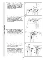
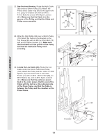
33. See inset drawing A. Route the Military 33 Press Cable (72) under a 90mm Pulley (15). Attach the Pulley and a Cable Trap (66) to the upper hole in the Long "U"-bracket (57) with an M10 x 47mm Bolt (12) and an M10 Nylon Locknut (21). Make sure that the Cable is in the groove of the Pulley and that the Cable and Pulley move smoothly. See inset drawing B. Slide an M10 Washer (9) onto an M8 x 74mm Shoulder Bolt (103). Insert the Bolt through the Pivot Arm (101) from the indicated side. Slide a 13mm x 6mm Spacer (104) and the end of the Military Press Cable (72) onto the end of the Bolt. Thread an M8 Nylon Locknut (3) onto the Bolt. Make sure that the end of the Cable can pivot easily. 15 57 72 72 21 57 103 9 15 A 66 12 B 101 104 3 72 CABLE ASSEMBLY 34. Locate the Leg Press Cable (99). Attach the 34 end of the Leg Press Cable to the Long "U"- bracket (57) with an M8 Nylon Locknut (3) and an M8 Washer (8). Do not completely tighten the Locknut. It should be threaded onto the end of the Cable so that only two threads are showing past the Locknut, as shown in the inset drawing. Wrap the Leg Press Cable (99) under a 90mm Pulley (15). Attach the Pulley to the Leg Press Upright (56) with the M10 x 90mm Bolt (16), an M10 Washer (9), and an M10 Nylon Locknut (21). The ball on the Cable must be on the indicated side of the Pulley. Make sure that the Cable and Pulley move smoothly and that the Cable is between the Pulley and the welded rod. 3 8 57 16 15 99 Welded 3 Rod 99 57 17 56 Ball 9 21
-
 1
1 -
2
-
3
-
4
-
5
-
6
-
7
-
8
-
9
-
10
-
11
-
 12
12 -
 13
13 -
 14
14 -
 15
15 -
 16
16 -
 17
17 -
 18
18 -
 19
19 -
 20
20 -
 21
21 -
 22
22 -
23
-
24
-
25
-
26
-
27
-
28
-
29
-
30
-
31
-
32
-
33
-
34
 |
 |
