Yamaha 03D Owner's Manual - Page 13
R Applications, Wordclock Connection and Termination
 |
View all Yamaha 03D manuals
Add to My Manuals
Save this manual to your list of manuals |
Page 13 highlights
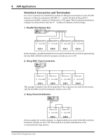
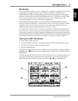
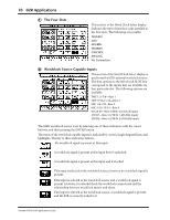
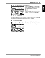
8 02R Applications Wordclock Connection and Termination For correct operation it is essential that wordclock cabling be terminated correctly. The 02R features a wordclock termination ON/OFF (75Ω) switch. Wordclock IN and OUT connections use BNC connectors. Wordclock is a TTL signal. Three wordclock distribution examples are shown below. Note the 75Ω wordclock terminator switch settings. 1. Parallel Distribution Box WORDCLOCK OUT Distribution box WORDCLOCK IN 75Ω Switch=ON WORDCLOCK IN 75Ω Switch=ON WORDCLOCK IN 75Ω Switch=ON WORDCLOCK IN 75Ω Switch=ON 02R-A 02R-B 02R-C 02R-D In this example, a parallel distribution box is used to distribute the wordclock signal among the four 02Rs. All 02R wordclock terminator switches are set to ON. 2. Using BNC T-bar Connectors WORDCLOCK OUT IN WORDCLOCK 75Ω Switch=OFF IN WORDCLOCK 75Ω Switch=OFF IN WORDCLOCK 75Ω Switch=OFF IN WORDCLOCK 75Ω Switch=ON 02R-A 02R-B 02R-C 02R-D This example is similar to the above except that T-bar connectors are used. In this system, only the last 02R's wordclock terminator switch is set to ON. 3. Daisy Chain Distribution WORDCLOCK OUT IN OUT WORDCLOCK 75Ω Switch=ON IN OUT WORDCLOCK 75Ω Switch=ON 02R-A 02R-B In this example, the wordclock master is a digital multitrack recorder. Both 02R wordclock terminator switches are set to ON. This method of wordclock distribution is not recommended for large systems. Yamaha 02R & 03D Applications Guide
-
 1
1 -
2
-
3
-
4
-
5
-
6
-
7
-
 8
8 -
 9
9 -
 10
10 -
 11
11 -
 12
12 -
 13
13 -
 14
14 -
 15
15 -
 16
16 -
 17
17 -
 18
18 -
19
-
20
-
21
-
22
-
23
-
24
-
25
-
26
-
27
-
28
-
29
-
30
-
31
-
32
-
33
-
34
-
35
-
36
-
37
-
38
-
39
-
40
-
41
-
42
-
43
-
44
-
45
-
46
-
47
-
48
-
49
-
50
-
51
-
52
-
53
-
54
-
55
-
56
-
57
-
58
-
59
-
60
-
61
-
62
-
63
-
64
-
65
-
66
-
67
-
68
-
69
-
70
-
71
-
72
-
73
-
74
-
75
-
76
-
77
-
78
-
79
-
80
-
81
-
82
-
83
-
84
-
85
-
86
-
87
-
88
-
89
 |
 |
