Yamaha 03D Owner's Manual - Page 64
D Applications, Wordclock Connections & Termination
 |
View all Yamaha 03D manuals
Add to My Manuals
Save this manual to your list of manuals |
Page 64 highlights
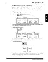
03D Applications 59 Wordclock Connections & Termination For correct operation it is essential that the wordclock cabling be terminated correctly. The 03D has a wordclock termination ON/OFF (75Ω) switch on the rear panel. Wordclock is a TTL signal, and IN and OUT connections use BNC connectors. Three wordclock distribution examples are shown below. Note the 75Ω wordclock terminator switch settings. 1. Parallel Distribution Box WORDCLOCK OUT Distribution box 03D WORDCLOCK IN 75Ω Switch=ON 03D-A WORDCLOCK IN 75Ω Switch=ON 03D-B WORDCLOCK IN 75Ω Switch=ON Other Device-A WORDCLOCK IN 75Ω Switch=ON Other Device-B In this example, a parallel distribution box is used to distribute the wordclock signal among devices. All wordclock terminator switches are set to ON. 2. Using BNC T-bar Connectors WORDCLOCK OUT WORDCLOCK IN 75Ω Switch=OFF WORDCLOCK IN 75Ω Switch=OFF WORDCLOCK IN 75Ω Switch=OFF WORDCLOCK IN 75Ω Switch=ON 03D-A 03D-B Other Device-A Other Device-B This example is similar to the above except that T-bar connectors are used. In this system, only the last device's wordclock terminator switch is set to ON. 3. Daisy Chain Distribution WORDCLOCK OUT IN OUT WORDCLOCK 75Ω Switch=ON 03D-A IN OUT WORDCLOCK 75Ω Switch=ON 03D-B In this example, the wordclock master is a digital multitrack recorder. Both 03D wordclock terminator switches are set to ON. This method of wordclock distribution is not recommended for large systems. Yamaha 02R & 03D Applications Guide
-
 1
1 -
2
-
3
-
4
-
5
-
6
-
7
-
8
-
9
-
10
-
11
-
12
-
13
-
14
-
15
-
16
-
17
-
18
-
19
-
20
-
21
-
22
-
23
-
24
-
25
-
26
-
27
-
28
-
29
-
30
-
31
-
32
-
33
-
34
-
35
-
36
-
37
-
38
-
39
-
40
-
41
-
42
-
43
-
44
-
45
-
46
-
47
-
48
-
49
-
50
-
51
-
52
-
53
-
54
-
55
-
56
-
57
-
58
-
 59
59 -
 60
60 -
 61
61 -
 62
62 -
 63
63 -
 64
64 -
 65
65 -
 66
66 -
 67
67 -
 68
68 -
 69
69 -
70
-
71
-
72
-
73
-
74
-
75
-
76
-
77
-
78
-
79
-
80
-
81
-
82
-
83
-
84
-
85
-
86
-
87
-
88
-
89
 |
 |
