Yamaha 03D Owner's Manual - Page 40
Two 02Rs with Four DA-88s
 |
View all Yamaha 03D manuals
Add to My Manuals
Save this manual to your list of manuals |
Page 40 highlights
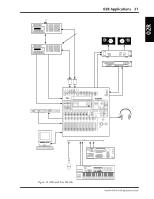
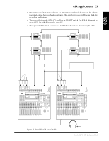
PW-88DL 25 pin cables x2 PW-88DL 25 pin cables x2 02R 02R Applications 35 • On the Tascam (CD8-TD) card there is a DIP switch that should be set to 16-bit. This is the initial setting, but you should confirm it. This switch is for use with Tascam High-Bit recording applications. • The rear of the Cascade (CD8-CS) card has an IN/OUT switch. For 02R-A this must be set to OUT. On 02R-B it must be set to IN. • The optional CD8-CS kit contains two CD8-CS cards and one 25-pin straight cable. PW-88S 15-pin cable DA-88-B ID=1 TDIF-1 DA-88-A ID=0 TDIF-1 SYNC OUT SYNC IN PW-88S 15-pin cable SYNC OUT DA-88-C ID=2 TDIF-1 DA-88-D ID=3 TDIF-1 SYNC IN SYNC OUT PW-88S 15-pin cable SYNC IN WC OUT (BNC) SMPTE OUT or MTC OUT (phono) Optional SY-88 Sync Board installed Rear panel DIP switches 2 and 5=O SMPTE timecode Wordclock or MTC SYNC OUT Terminator The power amp, monitors, and DAT recorder have been removed from this diagram for clarity. CD8-TD Switch=OUT WORD 123 CD8-CS CLOCK IN (BNC) (75Ω=ON) CD8-TD 25-pin straight cable SMPTE TIMECODE INPUT (phono) Switch=IN 123 CD8-CS SMPTE TIMECODE INPUT (phono) DIGITAL RECORDING CONSOLE DIGITAL RECORDING CONSOLE 02R-A WORD CLOCK OUT (BNC) 02R-B WORD CLOCK IN (BNC) (75Ω=ON) Figure 12 Two 02Rs with Four DA-88s Stereo fader, Bus master, & Aux master controls on this 02R are used. Yamaha 02R & 03D Applications Guide
-
 1
1 -
2
-
3
-
4
-
5
-
6
-
7
-
8
-
9
-
10
-
11
-
12
-
13
-
14
-
15
-
16
-
17
-
18
-
19
-
20
-
21
-
22
-
23
-
24
-
25
-
26
-
27
-
28
-
29
-
30
-
31
-
32
-
33
-
34
-
 35
35 -
 36
36 -
 37
37 -
 38
38 -
 39
39 -
 40
40 -
 41
41 -
 42
42 -
 43
43 -
 44
44 -
 45
45 -
46
-
47
-
48
-
49
-
50
-
51
-
52
-
53
-
54
-
55
-
56
-
57
-
58
-
59
-
60
-
61
-
62
-
63
-
64
-
65
-
66
-
67
-
68
-
69
-
70
-
71
-
72
-
73
-
74
-
75
-
76
-
77
-
78
-
79
-
80
-
81
-
82
-
83
-
84
-
85
-
86
-
87
-
88
-
89
 |
 |
