Yamaha AW4416 Reference Guide - Page 57
Screen functions], Channel, Bus assign buttons 1, ST stereo bus assign buttons, PAN knobs
 |
View all Yamaha AW4416 manuals
Add to My Manuals
Save this manual to your list of manuals |
Page 57 highlights
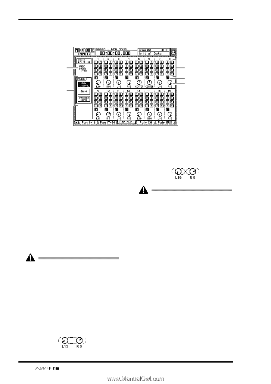
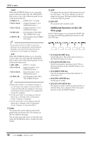
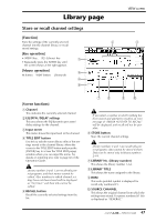
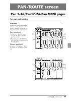
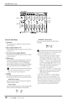
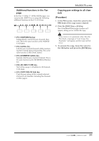
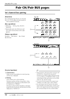
PAN/ROUTE screen q Pan MONI 1 2 3 4 5 [Screen functions] A Channel This indicates the channel for which pan/routing is being set. B Bus assign buttons 1-8 These buttons assign the signal of each channel to buses 1-8. C ST (stereo bus assign) buttons These buttons assign the signal of each channel to the stereo bus. D PAN knobs These knobs pan the signal between L/R of the stereo bus and between odd-numbered and even-numbered buses. Use the [DATA/JOG] dial to operate the knobs. Pressing the [ENTER] key will set the knob to the CENTER position. The ST OUT knobs in the Pan 17-24 page adjust the output channel balance. E MODE Use the following three buttons to select how the PAN knob will function for paired channels. q INDIVIDUAL button The pan of each channel will operate independently. (Default setting) q GANG button The pan of paired channels will be linked while preserving the existing spatial relationship. q INVERTED GANG button The pan of paired channels will be linked inversely. On the AW4416, the pan of a channel can be adjusted in the following two ways. (1).Use the [SEL] keys to select the desired channel, and rotate the [PAN] control. If AUTO PAN DISPLAY is turned "ON" in the UTILITY screen Prefer.1 page ([UTILITY] key ¡ [F2] key), operating the [PAN] control will automatically switch the display to the PAN/ROUTE screen even if a screen other than the PAN/ROUTE screen had been displayed. (2).In the PAN 1-16/PAN 17-24/PAN MONI pages, move the cursor to the PAN knob of the desired channel and rotate the [DATA/JOG] dial. In the PAN 1-16/PAN 17-24/PAN MONI pages, the channel can be specified freely, regardless of the state of the [SEL] keys. For this reason, there may be cases in which the channel whose pan is adjusted by the [PAN] control is different than the channel whose pan is adjusted by the [DATA/JOG] dial. 50 - Reference Guide
-
 1
1 -
2
-
3
-
4
-
5
-
6
-
7
-
8
-
9
-
10
-
11
-
12
-
13
-
14
-
15
-
16
-
17
-
18
-
19
-
20
-
21
-
22
-
23
-
24
-
25
-
26
-
27
-
28
-
29
-
30
-
31
-
32
-
33
-
34
-
35
-
36
-
37
-
38
-
39
-
40
-
41
-
42
-
43
-
44
-
45
-
46
-
47
-
48
-
49
-
50
-
51
-
 52
52 -
 53
53 -
 54
54 -
 55
55 -
 56
56 -
 57
57 -
 58
58 -
 59
59 -
 60
60 -
 61
61 -
 62
62 -
63
-
64
-
65
-
66
-
67
-
68
-
69
-
70
-
71
-
72
-
73
-
74
-
75
-
76
-
77
-
78
-
79
-
80
-
81
-
82
-
83
-
84
-
85
-
86
-
87
-
88
-
89
-
90
-
91
-
92
-
93
-
94
-
95
-
96
-
97
-
98
-
99
-
100
-
101
-
102
-
103
-
104
-
105
-
106
-
107
-
108
-
109
-
110
-
111
-
112
-
113
-
114
-
115
-
116
-
117
-
118
-
119
-
120
-
121
-
122
-
123
-
124
-
125
-
126
-
127
-
128
-
129
-
130
-
131
-
132
-
133
-
134
-
135
-
136
-
137
-
138
-
139
-
140
-
141
-
142
-
143
-
144
-
145
-
146
-
147
-
148
-
149
-
150
-
151
-
152
-
153
-
154
-
155
-
156
-
157
-
158
-
159
-
160
-
161
-
162
-
163
-
164
-
165
-
166
-
167
-
168
-
169
-
170
-
171
-
172
-
173
-
174
-
175
-
176
-
177
-
178
-
179
-
180
-
181
-
182
-
183
-
184
-
185
-
186
-
187
-
188
-
189
-
190
-
191
 |
 |