Yamaha CLP-950 Owner's Manual - Page 52
Montieren Sie die Rückwand E.
 |
View all Yamaha CLP-950 manuals
Add to My Manuals
Save this manual to your list of manuals |
Page 52 highlights
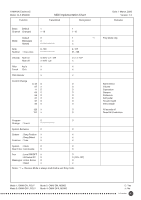
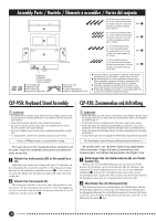
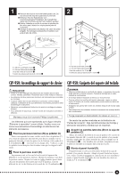
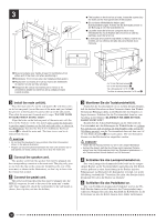
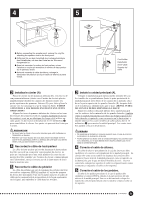
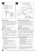
6 7 G A voltage selector is provided in some areas. G Spannungswähler (nur in bestimmten Verkaufsgebieten) G Un sélecteur de tension est prévu pour certaines régions G El selector de tensión está provisto para ciertos destinos. 4 x 12 mm round-head screws 2 4 x 12 mm Halbrundschrauben 2 Vis à tête ronde de 4 x 12 mm 2 Tornillos de cabeza redonda de 4 x 12 mm 2 B E 240 220 110 127 4 x 20 mm tapping screws 4 4 x 20 mm Schneidschrauben 4 Vis auto-taraudeuses 4 x 20 mm 4 Tornillos de autoenrosque de 4 x 20 mm 4 N Voltage Selector Before connecting the AC power cord, check the setting of the voltage selector which is provided in some areas. To set the selector for 110V, 127V, 220V or 240V main voltages, use a "minus" screwdriver to rotate the selector dial so that the correct voltage for your region appears next to the pointer on the panel. The voltage selector is set at 240V when the unit is initially shipped. After the proper voltage has been selected, connect the AC power cord to the AC INLET. CAUTION • An improper voltage setting can cause serious damage to the Clavinova or result in improper operation. M Attach the rear panel (E). With the rear panel slightly angled as shown in the illustration, lower it onto the feet's protruding edge at the rear of the pedal box. At this time, run the AC power cord through the cutout on the rear panel. Then, secure the top of the rear panel to the side panel brackets using two 4 x 12 mm round-head screws 2. Finally, secure the bottom of the rear panel to the pedal box using four 4 x 20 mm tapping screws 4. Move the instrument to the location where it will be used and connect the AC power cord to an AC wall outlet. A plug adaptor may be also provided in some areas to match the pin configuration of the AC wall outlets in your area I After completing the assembly, please check the following. • Are there any parts left over? ➔ Review the assembly procedure and correct any errors. • Is the Clavinova clear of doors and other movable fixtures? ➔ Move the Clavinova to an appropriate location. • Does the Clavinova make a rattling noise when you shake it? ➔ Tighten all screws. • Are the pedal and power cords inserted securely into the sockets? ➔ Check the connection. • If the main unit creaks or is otherwise unsteady when you play on the keyboard, refer to the assembly diagrams and retighten all screws. G After assembly is complete, it will be necessary to remove the keyboard string. This procedure is performed once only and the string will never have to be reattached again. For instructions on its removal, refer to the paper titled "REQUEST" that can be found on the keys underneath the key cover (see page 10). N Den Spannungswähler einstellen. Bevor Sie nun das Netzkabel anschließen, müssen Sie den Spannungswähler (falls vorhanden) auf die örtliche Netzspannung einstellen. Zum Verstellen drehen Sie den Spannungswähler mit einem Schlitzschraubendreher, bis der richtige Spannungswert (110, 127, 220 oder 240) an der Pfeilmarkierung steht. Bei der Auslieferung werden alle Instrumente mit Spannungswähler auf "240" voreingestellt. Nachdem Sie den Spannungswähler auf den richtigen Spannungswert eingestellt haben, stecken Sie das Netzkabel in die AC INLET-Buchse. VORSICHT • Eine falsche Spannungseinstellung kann das Clavinova schwer beschädigen und Funktionsstörungen zur Folge haben. M Montieren Sie die Rückwand (E). Setzen Sie die Rückwand leicht abgewinkelt, wie in der Abbildung gezeigt, hinter dem Pedalkasten auf die hervorspringenden Teile der Füße auf. Verlegen Sie das Netzkabel dabei durch den Ausschnitt in der Rückwand. Schrauben Sie dann die Rückwand oben mit zwei 4 x 12 mm Halbrundschrauben 2 fest. Schrauben Sie die Rückwand abschließend noch mit vier 4 x 20 mm Schneidschrauben 4 an den Pedalkasten. Bringen Sie das Instrument an seinen Stellplatz, und schließen Sie das Netzkabel an eine Steckdose an. In manchen Gebieten wird ein Steckerdapter mitgeliefert, um den Anschluß an die evtl. unterschiedlich geformte Steckdose zu ermöglichen. I Wenn der Zusammenbau beendet ist, prüfen Sie bitte folgende Dinge: • Sind Teile übrig geblieben? ➔ Gehen Sie den Vorgang des Zusammenbaus noch einmal durch und korrigieren Sie eventuelle Fehler. • Befindet sich das Clavinova weit genug von Türen und anderen beweglichen Vorrichtungen entfernt? ➔ Bewegen Sie das Clavinova an einen entsprechend sicheren Ort. • Macht das Clavinova Klappergeräusche, wenn Sie es schütteln? ➔ Ziehen Sie alle Schrauben fest. • Sind Pedal-und Netzkabel richtig an den Buchsen angeschlossen? ➔ Prüfen Sie die Verbindung. • Wenn die Haupteinheit knarrt oder beim Spielen wackelt, betrachten Sie die Abbildungen und ziehen Sie alle Schrauben noch einmal nach. G Nach dem Zusammenbau müssen Sie den Tastatur-Sicherungsdraht entfernen. Diese Arbeit wird nur einmal ausgeführt, und der Draht braucht später nicht wieder angebracht zu werden. Anweisungen hierzu entnehmen Sie bitte dem unter der Tastaturabdeckung auf den Tasten liegenden Hinweisblatt (siehe Seite 10). 52 CLP-950/930
-
 1
1 -
2
-
3
-
4
-
5
-
6
-
7
-
8
-
9
-
10
-
11
-
12
-
13
-
14
-
15
-
16
-
17
-
18
-
19
-
20
-
21
-
22
-
23
-
24
-
25
-
26
-
27
-
28
-
29
-
30
-
31
-
32
-
33
-
34
-
35
-
36
-
37
-
38
-
39
-
40
-
41
-
42
-
43
-
44
-
45
-
46
-
 47
47 -
 48
48 -
 49
49 -
 50
50 -
 51
51 -
 52
52 -
 53
53 -
 54
54 -
 55
55 -
 56
56 -
 57
57 -
58
-
59
-
60
-
61
-
62
-
63
-
64
-
65
-
66
 |
 |
