Yamaha DVX-S302 Owner's Manual - Page 12
Rear panel DVR-S300, U.K. and Europe models
 |
View all Yamaha DVX-S302 manuals
Add to My Manuals
Save this manual to your list of manuals |
Page 12 highlights
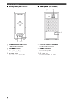
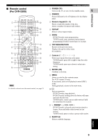
■ Rear panel (DVR-S300) (U.K. and Europe models) FUNCTIONAL OVERVIEW 1 INTRODUCTION 1 23 4 567 8 9 AV MONITOR OUT (DVD ONLY) VIDEO OUT (DVD ONLY) VIDEO Y S VIDEO PR PB COMPONENT DIGITAL IN L OPTICAL R PCM/DTS LINE OUT TV IN q DIGITAL AUX IN FM ANT GND AM ANT 75Ω UNBAL TO SUBWOOFER SYSTEM CONNECTOR 0 A B 1 AC power cord Connect to a standard AC outlet. 2 AV MONITOR OUT terminal (U.K. and Europe models only) Connect to your TV (see page 19). 3 VIDEO output terminal Connect to the video (composite) jack on your TV (see page 19). 4 COMPONENT VIDEO OUT terminal Connect the the Y PB/CB PR/CR jacks on your TV (see page 19). 5 LINE OUT terminal Connect to the AUDIO IN jacks on your VCR. 6 TV IN terminal Connect to the corresponding AUDIO OUT jacks on your TV (see page 19). 7 AUX IN terminal Connect to the AUDIO OUT jacks on your VCR or cassette deck. 8 FM ANT terminal Connect the FM antenna. 9 GND and AM ANT terminals Connect the AM loop antenna. 0 S VIDEO output terminal Connect to the S-video jack on your TV or VCR. A OPTICAL DIGITAL IN terminal Connect to the DIGITAL OUT jack on your digital audio component. B SYSTEM CONNECTOR terminal Connect the subwoofer. English 7
-
 1
1 -
2
-
3
-
4
-
5
-
6
-
 7
7 -
 8
8 -
 9
9 -
 10
10 -
 11
11 -
 12
12 -
 13
13 -
 14
14 -
 15
15 -
 16
16 -
 17
17 -
18
-
19
-
20
-
21
-
22
-
23
-
24
-
25
-
26
-
27
-
28
-
29
-
30
-
31
-
32
-
33
-
34
-
35
-
36
-
37
-
38
-
39
-
40
-
41
-
42
-
43
-
44
-
45
-
46
-
47
-
48
-
49
-
50
-
51
-
52
-
53
-
54
-
55
-
56
-
57
-
58
-
59
-
60
-
61
-
62
-
63
-
64
-
65
 |
 |
