Yamaha HTR-5460 Owner's Manual - Page 17
Connecting an External Decoder, English, INTRODUCTION, BASIC OPERA, ADVANCED, OPERATION, ADDITIONAL - surround system
 |
View all Yamaha HTR-5460 manuals
Add to My Manuals
Save this manual to your list of manuals |
Page 17 highlights
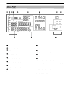
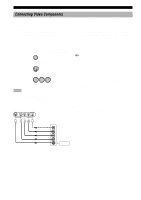
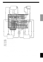
INTRODUCTION OUTPUT CD player CONNECTIONS MAIN OUTPUT SUBWOOFER OUTPUT External decoder LR (U.S.A. model) COAXIAL OUTPUT C LR LR SURROUND OUTPUT CENTER OUTPUT DIGITAL INPUT CD GND AM ANT GND COAXIAL OPTICAL D-TV/CBL DVD 6CH INPUT MAIN SURROUND CENTER L L MD/CD-R OPTICAL MD/CD-R R L R SUB WOOFER TUNER FM ANT DVD D-TV/CBL 75 UNBAL. DVD D-TV/CBL MONITOR OUT Y PB/CB PR/CR COMPONENT VIDEO IN VCR 1OUT IN V/DCVRR2OUT MONITOR OUT VIDEO VIDEO SIGNAL S VIDEO DIGITAL OUTPUT R PHONO CD IN(PLAY) OUT(REC) MD/CD-R DVD D-TV/CBL AUDIO SIGNAL IN OUT VCR 1 IN OUT VCR 2/DVR SUB WOOFER OUTPUT PREPARATION BASIC OPERATION ADVANCED OPERATION ADDITIONAL INFORMATION LR GND Turntable OUTPUT O LR INPUT LR O OUTPUT OPTICAL INPUT MD recorder or CD recorder OPTICAL OUTPUT indicates signal direction L indicates left analog cables R indicates right analog cables O indicates optical cables C indicates coaxial cables Connecting an External Decoder This unit is equipped with 6 additional input jacks (left and right MAIN, CENTER, left and right SURROUND and SUBWOOFER) for discrete multi-channel input from an external decoder, sound processor or pre-amplifier. Connect the output jacks on your external decoder to the 6CH INPUT jacks. Be sure to match the left and right outputs to the left and right input jacks for the main and surround channels. Notes • When you select 6CH INPUT as the input source, this unit automatically turns off the digital sound field processor, and you cannot listen to DSP programs. • When you select 6CH INPUT as the input source, changing items 1A to 1E on the SET MENU is not affected. 13 APPENDIX English
-
 1
1 -
2
-
3
-
4
-
5
-
6
-
7
-
8
-
9
-
10
-
11
-
 12
12 -
 13
13 -
 14
14 -
 15
15 -
 16
16 -
 17
17 -
 18
18 -
 19
19 -
 20
20 -
 21
21 -
 22
22 -
23
-
24
-
25
-
26
-
27
-
28
-
29
-
30
-
31
-
32
-
33
-
34
-
35
-
36
-
37
-
38
-
39
-
40
-
41
-
42
-
43
-
44
-
45
-
46
-
47
-
48
-
49
-
50
-
51
-
52
-
53
-
54
-
55
-
56
-
57
-
58
-
59
-
60
-
61
-
62
-
63
-
64
-
65
-
66
-
67
-
68
-
69
-
70
-
71
-
72
-
73
-
74
-
75
-
76
-
77
-
78
-
79
 |
 |
