Yamaha IMX644 Imx644 Manager Owner's Manual - Page 18
BLOCK] tab, INPUT] tab, MATRIX] tab, MISC] tab, GPI] tab, MEMORY] tab, Opens the OUTPUT EQ screen
 |
View all Yamaha IMX644 manuals
Add to My Manuals
Save this manual to your list of manuals |
Page 18 highlights
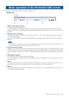
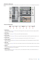
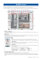
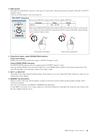
• Parameter editing area Here you can use mouse operations to visually edit the various parameters. The screen that is shown will depend on the tab that's selected. • Screen switching tabs 1 2 3 4 5 6 7 8 1 [BLOCK] tab Opens the BLOCK screen (page 19). This shows a block diagram of the entire signal route from input to output, and allows you to make parameter settings. 2 [INPUT] tab Opens the INPUT screen (page 23). Here you can edit the input channel parameters. 3 [MATRIX] tab Opens the MATRIX screen (page 24). Here you can specify the output channels to which the input channel signals are sent. 4 [OUTPUT] tab Opens the OUTPUT screen (page 25). Here you can edit parameters other than EQ for OUTPUT channels 1-4. 5 [OUTPUT EQ] tab Opens the OUTPUT EQ screen (page 26). Here you can edit the parameters of the 6-band equalizers provided for OUTPUT channels 1 through 4. 6 [MISC] tab Opens the MISC screen (page 28). Here you can edit settings for functions such as Priority Ducker, Music Override, and Feedback Suppressor. 7 [GPI] tab Opens the GPI screen (page 30). Here you can specify the memory that will be recalled for each input port of the GPI connector, and the make/open status for each output port. 8 [MEMORY] tab Opens the MEMORY screen (page 31). Here you can save your edited parameter settings in sixteen different memories, or recall previously-saved settings. IMX644 Manager Owner's Manual 18
-
 1
1 -
2
-
3
-
4
-
5
-
6
-
7
-
8
-
9
-
10
-
11
-
12
-
 13
13 -
 14
14 -
 15
15 -
 16
16 -
 17
17 -
 18
18 -
 19
19 -
 20
20 -
 21
21 -
 22
22 -
 23
23 -
24
-
25
-
26
-
27
-
28
-
29
-
30
-
31
-
32
-
33
-
34
-
35
 |
 |
