Yamaha IMX644 Imx644 Manager Owner's Manual - Page 22
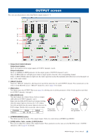
BAL] button, Output level meter, output SIGNAL/PEAK indicator, OUT 1-4, REC OUT, BALANCE dialog box
 |
View all Yamaha IMX644 manuals
Add to My Manuals
Save this manual to your list of manuals |
Page 22 highlights
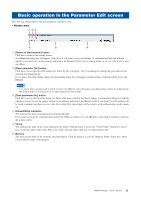
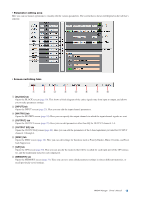
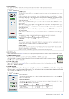
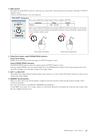
) [BAL] button This opens the "BALANCE" dialog box, allowing you to specify the volume balance between outputs A/B (L/R) of OUTPUT channels 1 and 2. Click the [CLOSE] button to close the dialog box. "BALANCE" dialog box Here you can adjust the volume balance between outputs A/B (L/R). Parameter Balance Range 0dB - -20.1dB Default 0dB Right-click the [BALANCE] knob and continue holding down the mouse button to decrease the A (L) volume; left-click and hold down the mouse button to decrease the B (R) volume. Doubleclick to reset the value to center. Press (hold) the left button Press (hold) the right button ! Output level meter, output SIGNAL/PEAK indicator Output level meters Displays the levels of the signal being output via OUTPUT channels 1 and 2. Output SIGNAL/PEAK indicators The SIGNAL/PEAK indicators show the output signal for OUTPUT channels 3 and 4. If the top segment (PEAK) of the level meter lights red, or if the PEAK indicator lights red, the output signal level is at the allowable maximum. Lower the input volume or the output volume. @ OUT 1-4, REC OUT These indicate the output channels and their names. Click a name to access the "Output Port Name" dialog box, where you can edit the name of the channel. # MEMORY [A]-[D] buttons When you click a button [A]-[D], the memory assigned to that button will be recalled and the parameter settings will be switched accordingly. This is the same function as the IMX644's MEMORY [A]-[D] buttons. Use the MISC screen (page 28) to assign a memory to each button. Memories A through D all contain the same settings when the unit is shipped from the factory. IMX644 Manager Owner's Manual 22
-
 1
1 -
2
-
3
-
4
-
5
-
6
-
7
-
8
-
9
-
10
-
11
-
12
-
13
-
14
-
15
-
16
-
 17
17 -
 18
18 -
 19
19 -
 20
20 -
 21
21 -
 22
22 -
 23
23 -
 24
24 -
 25
25 -
 26
26 -
 27
27 -
28
-
29
-
30
-
31
-
32
-
33
-
34
-
35
 |
 |
