Yamaha IMX644 Imx644 Manager Owner's Manual - Page 27
EQ response curve, Parameter indication F/G/Q
 |
View all Yamaha IMX644 manuals
Add to My Manuals
Save this manual to your list of manuals |
Page 27 highlights
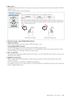
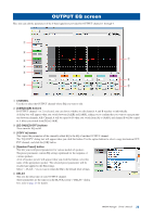
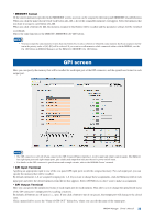
7 EQ response curve This indicates the frequency response of the current EQ settings. This is an approximate curve for your reference. The markers ( ) indicate the parameter values for each band. The color of the markers corresponds to the band number (1-6) shown below. By dragging a marker (left-click and move the mouse while holding down the button) you can specify the EQ response quickly and visually. Use the parameter indications below to make fine adjustments to the values. 8 Type The following EQ types can be specified for each band. Type P.EQ (Peaking EQ) HPF (High Pass Filter) LPF (Low Pass Filter) L.Shelf (Low Shelving EQ) H.Shelf (High Shelving EQ) Parameter F G Q F Slope Q F Slope Q F G F G Range 40Hz - 18kHz -15dB - +15dB 0.5 - 12.0 40Hz - 18kHz 12dB/oct (Fixed) 0.7 (Fixed) 40Hz - 18kHz 12dB/oct (Fixed) 0.7 (Fixed) 40Hz - 18kHz -15dB - +15dB 40Hz - 18kHz -15dB - +15dB The default setting is [P.EQ] with the following parameter values. Parameter Default Q 0.7 (common to all bands) G 0.0dB(common to all bands) F1 40Hz F2 100Hz F3 500Hz F4 2kHz F5 5kHz F6 10kHz 9 Parameter indication (F/G/Q) These indicate the center/cutoff frequency (F), gain (G), and Q. To edit the values, click the [ ]/[ ] buttons or use the mouse to drag the markers ( ) in the EQ response curve display. IMX644 Manager Owner's Manual 27
-
 1
1 -
2
-
3
-
4
-
5
-
6
-
7
-
8
-
9
-
10
-
11
-
12
-
13
-
14
-
15
-
16
-
17
-
18
-
19
-
20
-
21
-
 22
22 -
 23
23 -
 24
24 -
 25
25 -
 26
26 -
 27
27 -
 28
28 -
 29
29 -
 30
30 -
 31
31 -
 32
32 -
33
-
34
-
35
 |
 |
