Yamaha Q2031A Q2031A Owners Manual Image - Page 4
Precautions, Front, Panel
 |
View all Yamaha Q2031A manuals
Add to My Manuals
Save this manual to your list of manuals |
Page 4 highlights
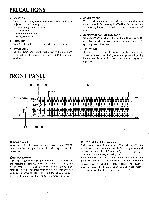
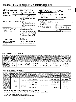
PRECAUTIONS • LOCATION Do not install the Q2031A in location where it might be subjected to the following; o Direct sunlight or excessive heat o Extreme cold o High humidity or dust o Strong vibrations • HANDLING Do not apply undue force to the switches or controls. • POWER CORD Pull the power cord from the wall outlet by the plug only. Never pull on the cord as this may lead to breaking or shorting. • CONNECTIONS Turn off all equipment power switches before making any connections. Before moving the Q2031A, disconnect cords to other equipment to avoid damaging connectors and cables. • CABINET CLEANING AND CARE Wipe the Q2031A cabinet clean with a soft, dry cloth. Do not clean it with benzene or other solvents and avoid spraying insecticides near it. • LIGHTNING If your area is prone to lightning strikes, unplug the Q2031A power cord during storms to prevent lightning induced transients on the power lines from damaging the equipment. FRONT PANEL 00 0 o YAMAHA GRAPHIC EQUALIZE MODEL O203IA O POWER ALON/10 F ANGE O HPF O EO O O 0 .5 40 50 8.3 BO 00 I 60 &.10 800 26k CH A CH B POWER switch When this switch is pressed to turn power on, the POWER indicator LED will light. Pressing the switch again turns the power off. 0 RANGE switches The RANGE switches select the filter boost or cut range for the respective channels. When the switches are off, the normal range of +/-12 dB is selected; when on, the +/-6 dB range is selected. This latter range is useful for very accurate equalization. When the Range switch is on, the LED indicator to its left lights to show that the +/-6 dB range is in effect. 0HPF (High Pass Filter) switches Each channel has an independent HPF switch to switch the HPF in or out of the audio path before the graphic equalizer section. With the HPF switch off, the input signal goes directly to the equalizer, bypassing the HPF. When the HPF switch is on, the HPF is switched into the audio path and provides 12 dB per octave rolloff below the frequency set by the HPF frequency control 0 . LED indicators associated with each switch light when the switch is on to show that the HPF is being used. 3
-
 1
1 -
 2
2 -
 3
3 -
 4
4 -
 5
5 -
 6
6 -
 7
7 -
 8
8 -
 9
9 -
 10
10 -
11
-
12
-
13
-
14
-
15
-
16
-
17
-
18
-
19
-
20
 |
 |
