Yamaha Q2031A Q2031A Owners Manual Image - Page 6
Typical, Configurations
 |
View all Yamaha Q2031A manuals
Add to My Manuals
Save this manual to your list of manuals |
Page 6 highlights
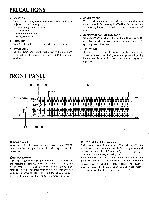
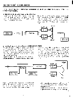
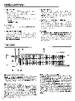
REAR PANEL 6 4) 11-• •• TRANS, URETER OUT-M -IN • IN UT LEVEL CAUTION: TO 010110 IIII NOI MAW, CH -*CH A ,,, I c, I ATTENTION: Ai IN n1 mDUO SI OUTPUT LEVEL n WAoRNING: 10 001101 1K VOl or 120V25W ®YAMAHA MODEL 0010 GRAPHIC MU/OZER O. O O U.S. & Canadian models 0 0 INPUT Connectors Both balanced (3-pin female XLR type connectors) and unbalanced (1/4" phone jacks) input connectors are available. A 600 ohm line should be used for both. Use the INPUT LEVEL switch to set the rated input level to either +4 dB or -20 dB. 0 OUTPUT LEVEL Switch Use this switch to set the rated nominal output level to correspond to the rated input level of the equipment to be connected. U.S. & Canadian models only O INPUT LEVEL Switch Use this switch to set the rated nominal input level to correspond to the rated output level of the equipment to be connected. @TRANSFORMER In/Out Switch This switch inserts the optional (See item 0) Input Transformers into the input stage, bypassing internal electronic balancing. @ OUTPUT Connectors Both balanced (3-pin male XLR type connectors) and unbalanced (1/4" phone jacks) output connectors are available. A 600 ohm lines should be used for the balanced XLR's and a 10k ohm line for the unbalanced 1/4" phone jacks. Use the OUTPUT LEVEL switch to set the rated nominal output level to either +4 or -20 dB. 0 Input Transformer Octal Sockets Two Octal , Sockets are provided to accept optional 15k to 15k ohm bridging Input Transformers. (BRT15K) °Internal Output Transformer (Optionals) The Output Transformer should be installed by a qualified service technicians. TYPICAL CONFIGURATIONS • Insertion between the channel (master) insert out/in MIXING CONSOLE Q2031A OUTPUT L R INSERT OUT INSERT IN POWER AMPS CH A INPUT CH A OUTPUT
-
 1
1 -
 2
2 -
 3
3 -
 4
4 -
 5
5 -
 6
6 -
 7
7 -
 8
8 -
 9
9 -
 10
10 -
 11
11 -
 12
12 -
13
-
14
-
15
-
16
-
17
-
18
-
19
-
20
 |
 |
