2012 Jeep Grand Cherokee User Guide - Page 130
2012 Jeep Grand Cherokee Manual

Page 130 highlights
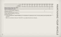
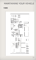
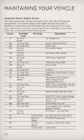
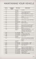
MAINTAINING YOUR VEHICLE Integrated Power Module (fuses) The integrated power module is located on the right side of the engine compartment. This center contains cartridge fuses and mini fuses. A description of each fuse and component may be stamped on the inside cover, otherwise the cavity number of each fuse is stamped on the inside cover that corresponds to the following chart. Cavity J01 J02 J03 J04 J05 J06 J07 J08 J09 J10 J11 J13 Cartridge Fuse 40 Amp Green 30 Amp Pink 30 Amp Pink 25 Amp Natural 25 Amp Natural 40 Amp Green 30 Amp Pink 40 Amp Green 30 Amp Pink 30 Amp Pink 30 Amp Pink 60 Amp Yellow 20 Amp Blue 40 Amp Green 40 Amp Green 20 Amp Blue 60 Amp Yellow 30 Amp Pink 20 Amp Blue 25 Amp Natural 15 Amp Blue 20 Amp Yellow 20 Amp Yellow 10 Amp Red Mini Fuse Description Air Suspension Power Liftgate Module Trailer Tow Driver Door Node Passenger Door Node ABS Pump Feed/ESP ABS Valve Feed/ESP Power Seat E-Brake Headlamp Wash Relay Contact DTCM Streaming Video Module/ VES3 Module/VES2 Module/DISP/DVD Trailer Tow Lamps/Park Lamps Rear Window Defroster Starter Motor Solenoid Feed NGC/PCM Transmission Range Rad Fan Motor HI/Rad Fan Motor Low Front Wiper Ground Front Washer Control/Rear Washer Control PWR Batt - Sunroof Mod Sw Stop Switch Lamp Feed ELSD/Air Suspension Liftgate Unlock/DRL Relay Trailer Tow J14 J15 J17 J18 J19 J20 J21 J22 M1 M2 M3 M4 128
-
 1
1 -
2
-
3
-
4
-
5
-
6
-
7
-
8
-
9
-
10
-
11
-
12
-
13
-
14
-
15
-
16
-
17
-
18
-
19
-
20
-
21
-
22
-
23
-
24
-
25
-
26
-
27
-
28
-
29
-
30
-
31
-
32
-
33
-
34
-
35
-
36
-
37
-
38
-
39
-
40
-
41
-
42
-
43
-
44
-
45
-
46
-
47
-
48
-
49
-
50
-
51
-
52
-
53
-
54
-
55
-
56
-
57
-
58
-
59
-
60
-
61
-
62
-
63
-
64
-
65
-
66
-
67
-
68
-
69
-
70
-
71
-
72
-
73
-
74
-
75
-
76
-
77
-
78
-
79
-
80
-
81
-
82
-
83
-
84
-
85
-
86
-
87
-
88
-
89
-
90
-
91
-
92
-
93
-
94
-
95
-
96
-
97
-
98
-
99
-
100
-
101
-
102
-
103
-
104
-
105
-
106
-
107
-
108
-
109
-
110
-
111
-
112
-
113
-
114
-
115
-
116
-
117
-
118
-
119
-
120
-
121
-
122
-
123
-
124
-
 125
125 -
 126
126 -
 127
127 -
 128
128 -
 129
129 -
 130
130 -
 131
131 -
 132
132 -
 133
133 -
 134
134 -
 135
135 -
136
-
137
-
138
-
139
-
140
-
141
-
142
-
143
-
144
-
145
-
146
-
147
-
148
 |
 |