Alpine IVA W200 Owners Manual - Page 70
Installation
 |
UPC - 793276200532
View all Alpine IVA W200 manuals
Add to My Manuals
Save this manual to your list of manuals |
Page 70 highlights
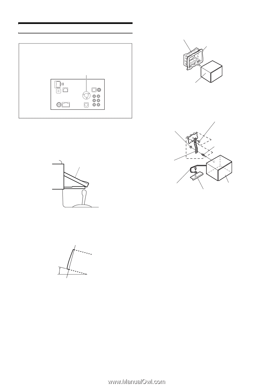
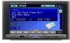
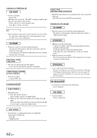
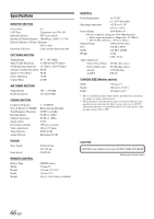
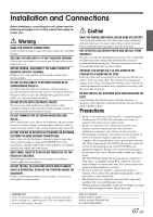
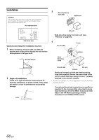
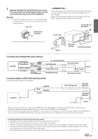
Installation Caution Do not block the unit's fan or heat sink, thus preventing air circulation. If blocked, heat will accumulate inside the unit and may cause a fire. Air ventilation hole 3 Mounting Sleeve (Included) Dashboard Side of the Unit Caution concerning the installation location 1 Before installing, check to make sure that the opening and closing of the display will not interfere with operation of the gear shift. Movable Display this unit Slide mounting sleeve from main unit (see "Removal" on page 69). 4 Hex Nut (M5) Screw *2 Bolt Stud Metal Mounting Strap *1 2 Angle of installation Install at an angle of between horizontal and 30°. Note that installing at an angle outside of this range will result in a loss of performance and possibly damage. 0 -30° Ground Lead Chassis this unit Reinforce the head unit with the metal mounting strap (not supplied). Secure the ground lead of the unit to a clean metal spot using a screw (*1) already attached to the vehicle's chassis. • For the screw marked "*2", use an appropriate screw for the chosen mounting location. Connect each input lead coming from an amplifier or equalizer to the corresponding output lead coming from the left rear of the IVA-W200. Connect all other leads of the IVA-W200 according to details described in the CONNECTlONS section. 68-EN
-
 1
1 -
2
-
3
-
4
-
5
-
6
-
7
-
8
-
9
-
10
-
11
-
12
-
13
-
14
-
15
-
16
-
17
-
18
-
19
-
20
-
21
-
22
-
23
-
24
-
25
-
26
-
27
-
28
-
29
-
30
-
31
-
32
-
33
-
34
-
35
-
36
-
37
-
38
-
39
-
40
-
41
-
42
-
43
-
44
-
45
-
46
-
47
-
48
-
49
-
50
-
51
-
52
-
53
-
54
-
55
-
56
-
57
-
58
-
59
-
60
-
61
-
62
-
63
-
64
-
 65
65 -
 66
66 -
 67
67 -
 68
68 -
 69
69 -
 70
70 -
 71
71 -
 72
72 -
 73
73 -
 74
74 -
 75
75 -
76
-
77
 |
 |