Asus A7V400-MX SE A7V400-MX SE user's manual for English version
Asus A7V400-MX SE Manual
 |
View all Asus A7V400-MX SE manuals
Add to My Manuals
Save this manual to your list of manuals |
Asus A7V400-MX SE manual content summary:
- Asus A7V400-MX SE | A7V400-MX SE user's manual for English version - Page 1
Motherboard A7V400-MX SE - Asus A7V400-MX SE | A7V400-MX SE user's manual for English version - Page 2
express written permission of ASUSTeK COMPUTER INC. ("ASUS"). Product warranty or service will not be extended if: (1) the ASUS HAS BEEN ADVISED OF THE POSSIBILITY OF SUCH DAMAGES ARISING FROM ANY DEFECT OR ERROR IN THIS MANUAL OR PRODUCT. SPECIFICATIONS AND INFORMATION CONTAINED IN THIS MANUAL - Asus A7V400-MX SE | A7V400-MX SE user's manual for English version - Page 3
guide vii A7V400-MX SE specifications summary viii Chapter 1: Product introduction 1.1 1.2 1.3 1.4 1.5 1.6 1.7 1.8 1.9 1.10 Welcome 1-2 Package contents 1-2 Special features 1-2 1.3.1 Product highlights 1-2 1.3.2 Innovative ASUS features 1-4 Before you proceed 1-5 Motherboard overview - Asus A7V400-MX SE | A7V400-MX SE user's manual for English version - Page 4
ASUS CrashFree BIOS utility 2-4 2.1.4 ASUS EZ Flash utility 2-4 2.1.5 ASUS Update utility 2-5 2.2 BIOS beep codes 2-7 2.3 BIOS setup program 2-7 2.3.1 BIOS menu bar 2-8 2.3.2 Legend bar 2-8 2.4 Main menu 2-10 2.5 Advanced menu 2-15 2.5.1 CPU Configuration 2-15 2.5.2 Memory Configuration - Asus A7V400-MX SE | A7V400-MX SE user's manual for English version - Page 5
. This equipment generates, uses and can radiate radio frequency energy and, if not installed and used in accordance with manufacturer's instructions, may cause harmful interference to radio communications. However, there is no guarantee that interference will not occur in a particular installation - Asus A7V400-MX SE | A7V400-MX SE user's manual for English version - Page 6
Contact a qualified service technician or your retailer. Operation safety • Before installing the motherboard and adding devices on it, carefully read all the manuals that came with . • If you encounter technical problems with the product, contact a qualified service technician or your retailer. vi - Asus A7V400-MX SE | A7V400-MX SE user's manual for English version - Page 7
certain tasks properly, take note of the following symbols used throughout this guide. W A R N I N G . Information to prevent injury software updates. 1. A S U S w e b s i t e s The ASUS websites worldwide provide updated information on ASUS hardware and software products. Refer to the ASUS contact - Asus A7V400-MX SE | A7V400-MX SE user's manual for English version - Page 8
A7V400-MX SE specifications summary CPU Socket A for AMD Athlon™ XP/Sempron™ processors Thoroughbred/Barton core support Chipset VIA KM400A VIA VT8237 (no RAID support) Front Side Bus (FSB) 400/333/266/200 MHz Memory 2 x 184-pin DDR DIMM sockets support up to maximum 2 GB unbuffered DDR400*/ - Asus A7V400-MX SE | A7V400-MX SE user's manual for English version - Page 9
A7V400-MX SE specifications summary Internal connectors (continuation) 1 x AUX connector 1 x Front panel audio connector CPU/chassis fan connectors ATX power connector Panel connector BIOS features 2 Mb Flash ROM, Phoenix Award BIOS, PnP, DMI2.0, WfM2.0, SM BIOS 2.3,ASUS EZ Flash, ASUS CrashFree - Asus A7V400-MX SE | A7V400-MX SE user's manual for English version - Page 10
x - Asus A7V400-MX SE | A7V400-MX SE user's manual for English version - Page 11
This chapter describes the motherboard features and the new technologies it supports. 1Product introduction - Asus A7V400-MX SE | A7V400-MX SE user's manual for English version - Page 12
following items. Motherboard ASUS A7V400-MX SE motherboard Cables Serial ATA signal cable and Serial ATA power cable Ultra DMA 133/100/66 cable Floppy disk drive cable Accessories I/O shield A p p l i c a t i o n C D s ASUS motherboard support CD D o c u m e n t a t i o n User guide If any - Asus A7V400-MX SE | A7V400-MX SE user's manual for English version - Page 13
The motherboard implements the Universal Serial Bus (USB) 2.0 specification, dramatically increasing the connection speed from the 12 Mbps bandwidth on USB 1.1 to a fast 480 Mbps on USB 2.0. USB 2.0 is backward compatible with USB 1.1. See pages 1-20 and 1-23 for details. ASUS A7V400-MX SE 1-3 - Asus A7V400-MX SE | A7V400-MX SE user's manual for English version - Page 14
file gets corrupted. This utility eliminates the need to buy a replacement ROM chip. See page 2-4 for details. ASUS EZ Flash BIOS With the ASUS EZ Flash, you can easily update the system BIOS even before loading the operating system. No need to use a DOS-based utility or boot from a floppy disk. See - Asus A7V400-MX SE | A7V400-MX SE user's manual for English version - Page 15
a reminder that you should shut down the system and unplug the power cable before removing or plugging in any motherboard component. The illustration below shows the location of the onboard LED. A7V400-MX SE A7V400-MX SE Onboard LED SB_PWR ON Standby Power OFF Powered Off ASUS A7V400-MX SE 1-5 - Asus A7V400-MX SE | A7V400-MX SE user's manual for English version - Page 16
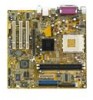
1.5 Motherboard overview 1.5.1 Motherboard layout 24.5cm (9.6in) PS/2KBMS T: Mouse B: Keyboard COM1 Socket 462 Port (AGP1) PCI1 A7V400-MX SE PCI2 CR2032 3V Lithium Cell CMOS Power VIA VT8237 PCI3 CLRTC USBPWR56 USBPWR78 SB_PWR AUX CD USB56 USB78 2Mbit ISA BIOS SATA2 SATA1 Super I/O - Asus A7V400-MX SE | A7V400-MX SE user's manual for English version - Page 17
chassis as indicated in the image below. 1.5.3 Screw holes Place eight (8) screws into the holes indicated by circles to secure the motherboard to the chassis. Do not overtighten the screws! Doing so can damage the motherboard. Place this side towards the rear of the chassis ASUS A7V400-MX SE 1-7 - Asus A7V400-MX SE | A7V400-MX SE user's manual for English version - Page 18
Processing Unit (CPU) 1.6.1 Overview The motherboard has a Socket A for installation. The Athlon™/Sempron™ CPU has a "marked" corner. motherboard does not support AMD processors with less than 1 GHz core speed. A7V400-MX SE CPU NOTCH TO INNER CORNER AMD™ CPU LOCK LEVER CPU NOTCH A7V400-MX SE - Asus A7V400-MX SE | A7V400-MX SE user's manual for English version - Page 19
104 Pins 80 Pins 1.7 System memory 1.7.1 Overview The motherboard has two Double Data Rate (DDR) DIMM sockets that support up to 2 GB unbuffered non-ECC DDR400*/333/266/200 DDR SDRAM DIMMs. Each DIMM socket is double-sided. A7V400-MX SE A7V400-MX SE 184-pin DDR DIMM sockets * You can install a - Asus A7V400-MX SE | A7V400-MX SE user's manual for English version - Page 20
DDR400 Qualified Vendors List Size Vendor 256 MB 512 MB 256 MB 512 MB 256 MB 512 MB 256 MB 512 MB 1024 MB 1024 MB 256 MB 512 MB 256 MB 256 MB 512 MB 512 MB 256 MB 512 MB 256 MB 512 MB 256 MB 512 MB 512 MB 1024 MB 256 MB 512 MB 256 MB 512 MB 256 MB 512 MB 256 MB 512 MB 1024 MB 256 MB 512 MB 256 MB - Asus A7V400-MX SE | A7V400-MX SE user's manual for English version - Page 21
GL3LC32G88TG-35 DS GL3LC32G88TG-35 SS GL3LC32G88TG-5A SS WLCSP Package SS N/A DS N/A SS C2S56D30TP-5 DS C2S56D30TP-5 S i d e ( s ): S S - Single-sided D S - Double-sided C L - CAS Latency Visit the ASUS website for the latest DDR400 Qualified Vendors List. ASUS A7V400-MX SE 1-11 - Asus A7V400-MX SE | A7V400-MX SE user's manual for English version - Page 22
-TCCC N2DS25680CT-6K N2DS25680CT-6K VT56DD32M8PC-6 VT56DD32M8PC-6 NT5DS32M8CT-6K NT5DS32M8CT-6K NT5DS64M8AF-6K S i d e ( s ): S S - Single-sided D S - Double-sided C L - CAS Latency Visit the ASUS website for the latest DDR333 Qualified Vendors List. 1-12 Chapter 1: Product introduction - Asus A7V400-MX SE | A7V400-MX SE user's manual for English version - Page 23
steps to remove a DIMM. 1. Simultaneously press the retaining clips outward to unlock the DIMM. Support the DIMM lightly with your fingers when pressing the retaining clips. The DIMM might get damaged when it flips out with extra force. 2. Remove the DIMM from the socket. ASUS A7V400-MX SE 1-13 - Asus A7V400-MX SE | A7V400-MX SE user's manual for English version - Page 24
the expansion cards that they support. Make sure to unplug the physical injury and damage motherboard components. 1.8.1 Installing Remove the system unit cover (if your motherboard is already installed in a chassis). 3. the necessary BIOS settings, if any. See Chapter 2 for information on BIOS setup. - Asus A7V400-MX SE | A7V400-MX SE user's manual for English version - Page 25
C used - - - D - used - - When using PCI cards on shared slots, ensure that the drivers support "Share IRQ" or that the cards do not need IRQ assignments; otherwise, conflicts will arise between the two PCI groups, making the system unstable and the card inoperable. ASUS A7V400-MX SE 1-15 - Asus A7V400-MX SE | A7V400-MX SE user's manual for English version - Page 26
that they fit into the AGP slot. A7V400-MX SE Keyed for 1.5v A7V400-MX SE Accelerated Graphics Port (AGP) 1.8.4 PCI slots The PCI slots support cards such as a LAN card, SCSI card, USB card, and other cards that comply with PCI specifications. The figure shows a LAN card installed on a PCI slot - Asus A7V400-MX SE | A7V400-MX SE user's manual for English version - Page 27
settings before installing the motherboard to the chassis. DSW O1 2 3 4 5 O1 2 3 4 5 N N O1 2 3 4 5 N (Default) O1 2 3 4 5 N CPU 200MHz 166.67MHz 133.33MHz 100MHz AGP 66.67MHz 66.67MHz 66.67MHz 66.67MHz PCI 33.33MHz 33.33MHz 33.33MHz 33.33MHz A7V400-MX SE A7V400-MX SE CPU external frequency - Asus A7V400-MX SE | A7V400-MX SE user's manual for English version - Page 28
in CMOS. You can clear the CMOS memory of date, time, and system setup BIOS setup to re-enter data. Except when clearing the RTC RAM, never remove the cap on CLRTC jumper default position. Removing the cap will cause system boot failure! A7V400-MX SE CLRTC 12 23 Clear CMOS Normal A7V400-MX SE - Asus A7V400-MX SE | A7V400-MX SE user's manual for English version - Page 29
USB device wake-up feature requires a power supply that can provide 500mA on the +5VSB lead for each USB port; otherwise, the system will not power up. • The total current consumed must NOT exceed the power supply capability (+5VSB) whether under normal condition or in sleep mode. ASUS A7V400-MX SE - Asus A7V400-MX SE | A7V400-MX SE user's manual for English version - Page 30
LAN) through a network hub. 4 . L i n e I n p o r t ( l i g h t b l u e ) . This port connects a tape, CD, DVD player or other audio (USB) ports are available for connecting USB 2.0 devices. 9 . V i d e o G r a p h i c s A d a p t e r p o r t . This 15-pin port is for a VGA monitor or other VGA- - Asus A7V400-MX SE | A7V400-MX SE user's manual for English version - Page 31
incorrect insertion when you connect the IDE cable. • Use the 80-conductor IDE cable for Ultra DMA 133/100/66 IDE devices. A7V400-MX SE A7V400-MX SE IDE connectors ASUS A7V400-MX SE PRI_IDE SEC_IDE NOTE: Orient the red markings (usually zigzag) on the IDE ribbon cable to PIN 1. PIN 1 1-21 - Asus A7V400-MX SE | A7V400-MX SE user's manual for English version - Page 32
RSATA_RXP1 RSATA_RXN1 GND A7V400-MX SE SATA connector Important notes on Serial ATA • You must install Windows® 2000 SP4, Windows® XP SP1, Windows® 2003, or newer OS versions before using Serial ATA hard disk drives. • The Serial ATA interface is not supported when using Windows® 98SE/Me operating - Asus A7V400-MX SE | A7V400-MX SE user's manual for English version - Page 33
purchased separately. USB+5V USB_P8USB_P8+ GND NC USB+5V USB_P6USB_P6+ GND NC USB+5V USB_P7USB_P7+ GND USB+5V USB_P5USB_P5+ GND A7V400-MX SE USB56 1 A7V400-MX SE USB connectors USB78 1 Never connect a 1 3 9 4 c a b l e to the USB connectors. Doing so will damage the motherboard! 6 . GAME - Asus A7V400-MX SE | A7V400-MX SE user's manual for English version - Page 34
stereo audio input from sound sources such as a CD-ROM, TV tuner, or MPEG card. AUX(White) CD(Black) A7V400-MX SE A7V400-MX SE Internal audio connectors 8 . Front panel audio connectors (10-1 pin FP_AUDIO) This connector is for the front panel audio daughterboard cable. This connector supports the - Asus A7V400-MX SE | A7V400-MX SE user's manual for English version - Page 35
back of the system chassis. The S/PDIF module is purchased separately. +5V SPDIFOUT GND A7V400-MX SE SPDIF A7V400-MX SE Digital audio connector 10. ATX power connector (20-pin ATXPWR) This connector is for the 20 difficulty powering up if the power supply is inadequate. ASUS A7V400-MX SE 1-25 - Asus A7V400-MX SE | A7V400-MX SE user's manual for English version - Page 36
supports several chassis-mounted functions. PLED SPEAKER +5 V PLED +5V Ground Ground Speaker HD_LED+ HD_LEDExtSMI# Ground PWRBIN Ground Reset Ground A7V400-MX SE RESET HDLED PWRBTN SMI * Requires an ATX power supply. A7V400-MX SE on the BIOS settings. Pressing allows you to manually place the - Asus A7V400-MX SE | A7V400-MX SE user's manual for English version - Page 37
This chapter tells how to change the system settings through the BIOS Setup menus. Detailed descriptions of the BIOS parameters are also provided. 2 BIOS setup - Asus A7V400-MX SE | A7V400-MX SE user's manual for English version - Page 38
fails or gets corrupted.) 3. ASUS EZ Flash (Updates the BIOS in DOS mode using a floppy disk.) 4. A S U S U p d a t e (Updates the BIOS in Windows® environment.) Refer to the corresponding sections for details on these utilities. Save a copy of the original motherboard BIOS file to a floppy disk in - Asus A7V400-MX SE | A7V400-MX SE user's manual for English version - Page 39
111122223333 Write OK 111122223333 No Update 111122223333 Write Fail Warning: Don't Turn OFF Power Or Reset System! ASUS A7V400-MX SE 2-3 - Asus A7V400-MX SE | A7V400-MX SE user's manual for English version - Page 40
. Follow the instructions in the previous section to update the BIOS. Before using the ASUS CrashFree BIOS feature on this motherboard, you must install an AGP or PCI VGA card to one of the expansion slots before you turn on the computer. Motherboards with onboard VGA (such as A7V400-MX SE) do not - Asus A7V400-MX SE | A7V400-MX SE user's manual for English version - Page 41
you to manage, save, and update the motherboard BIOS in Windows® environment. The ASUS Update utility allows you to: • Save the current BIOS file • Download the latest BIOS file from the Internet • Update the BIOS from an updated BIOS file • Update the BIOS directly from the Internet, and • View - Asus A7V400-MX SE | A7V400-MX SE user's manual for English version - Page 42
to download. Click Next. 5. Follow the screen instructions to complete the update process. The ASUS Update utility is capable of updating itself through the Internet. Always update the utility to avail all its features. Updating the BIOS through a BIOS file To update the BIOS through a BIOS file - Asus A7V400-MX SE | A7V400-MX SE user's manual for English version - Page 43
Video card not found or video card memory bad CPU overheated; System running at a lower frequency 2.3 BIOS setup program This motherboard supports a programmable low pin count (LPC) chip that you can update your selections from the available options using the navigation keys. ASUS A7V400-MX SE 2-7 - Asus A7V400-MX SE | A7V400-MX SE user's manual for English version - Page 44
your screen. • Visit the ASUS website (www.asus.com) to download the latest BIOS file for this motherboard. 2.3.1 BIOS menu bar The top of Function Displays the General Help screen Navigates the Item Specific Help screen Loads previous values Jumps to the Exit menu or returns to - Asus A7V400-MX SE | A7V400-MX SE user's manual for English version - Page 45
appear in the Item Help window located to the right of each menu. This window displays the help text for the highlighted field. Saving changes and exiting the Setup program See "2.8 Exit menu" for detailed information on saving changes and exiting the setup program. ASUS A7V400-MX SE 2-9 - Asus A7V400-MX SE | A7V400-MX SE user's manual for English version - Page 46
SATA Master Second SATA Master Installed Memory 15 : 30 : 30 Wed, Jan 05 2003 [1.44M, 3.5 in.] [ST321122A] [ASUS CDS520/A] [None] [None] [None] [None] 256MB Select Menu Item Specific in.] Installed Memory [XXX MB] This field automatically displays the amount of conventional memory detected by the - Asus A7V400-MX SE | A7V400-MX SE user's manual for English version - Page 47
Specific manually enter the hard disk drive values. Before attempting to configure a hard disk drive, make sure you have the correct configuration information supplied by the drive manufacturer. Incorrect settings may cause the system to fail to recognize the installed hard disk. ASUS A7V400-MX SE - Asus A7V400-MX SE | A7V400-MX SE user's manual for English version - Page 48
and [CHS] Settings Primary IDE Master Primary IDE Master Access Mode [Manual] [CHS] Capacity 40020 MB Cylinder Head Sector PIO Mode UDMA Mode Transfer Mode [19158] [ 16] [ 255] [ Auto] [ Auto] UDMA 4 Select Menu Item Specific Help Press [Enter] to select sector addressing method. F1 : Help - Asus A7V400-MX SE | A7V400-MX SE user's manual for English version - Page 49
IDE Primary Master field to [Manual] and the Access Mode to SATA hard disk drive as an extended IDE drive. Configuration options: [Auto] [None] Access Mode [Auto] The default [Auto] enables or disables the LBA mode for the SATA hard disk drive. Configuration options: [Auto] [Large] ASUS A7V400-MX SE - Asus A7V400-MX SE | A7V400-MX SE user's manual for English version - Page 50
Displays the precompressed volumes on the hard disk drive (in MB), if any. Landing Zone Displays the drive's maximum useable capacity as calculated by the BIOS based on the drive information you entered. Sector Refer to the previous section. 2-14 Chapter - Asus A7V400-MX SE | A7V400-MX SE user's manual for English version - Page 51
BIOS. CPU Configuration CPU Type CPU Speed Cache RAM Current FSB Frequency AMD Athlon(tm) 750MHz 256K 100MHz Select Menu Item Specific Help F1 : Help ↑↓ : Select Item -/+ : Change Value F5 : Setup Defaults ESC : Exit →← : Select Menu Enter : Select Sub-menu F10 : Save and Exit ASUS A7V400-MX - Asus A7V400-MX SE | A7V400-MX SE user's manual for English version - Page 52
2.5 Disabled 5T 7T 5T [4] [2T Command] [3T] [2T] Select Menu Item Specific Help Set DRAM frequency. F1 : Help ↑↓ : Select Item -/+ : Change Value Exit Current DRAM Frequency [XXX MHz] Displays the current memory frequency as auto-detected by the BIOS. DRAM Clock [By SPD] The DRAM clock are set - Asus A7V400-MX SE | A7V400-MX SE user's manual for English version - Page 53
switch [Auto] Init Display First [PCI Slot] AGP Bridge Configuration Select Menu Item Specific Help F1 : Help ↑↓ : Select Item -/+ : Change Value F5 : Setup the primary VGA type if your system has multiple video controllers. Configuration options: [PCI Slot] [AGP] ASUS A7V400-MX SE 2-17 - Asus A7V400-MX SE | A7V400-MX SE user's manual for English version - Page 54
Video Memory [64M] [4X] [Auto] DA [Disabled] [32M] Select Menu Item Specific or manually assign the AGP Driving Value. Configuration options: [Auto] [Manual] the AGP Driving Control to [Manual]. Press to assign Video Memory [32M] Allows you to set the share memory size for the onboard VGA. - Asus A7V400-MX SE | A7V400-MX SE user's manual for English version - Page 55
specification, PCI/ ISA PnP for devices compliant with the Plug and Play standard whether designed for PCI or ISA bus architecture. F1 : Help ↑↓ : Select Item -/+ : Change Value F5 : Setup Defaults ESC : Exit →← : Select Menu Enter : Select Sub-menu F10 : Save and Exit ASUS A7V400-MX SE 2-19 - Asus A7V400-MX SE | A7V400-MX SE user's manual for English version - Page 56
SATA controller. Configuration options: [Disabled] [Enabled] Disable the O n C h i p S A T A item when installing Windows® 98/Me operating system. AC97 Audio [Auto] This field allows you to enable or disable the onboard AC97 audio controller. Configuration options: [Auto] [Disabled] Onboard LAN - Asus A7V400-MX SE | A7V400-MX SE user's manual for English version - Page 57
ROM [Disabled] Allows you to turn on or off the onboard LAN boot ROM. This item appears only when onboard LAN is enabled. Configuration options: [Enabled] [Disabled] Serial Port1 Address [3F8 set the IRQ assignment for the onboard MIDI port. Configuration options: [5] [10] ASUS A7V400-MX SE 2-21 - Asus A7V400-MX SE | A7V400-MX SE user's manual for English version - Page 58
. USB Configuration OnChip USB Controller OnChip EHCI Controller USB Legacy Support [Enabled] [Enabled] [Enabled] Select Menu Item Specific Help USB EHCI controller. Configuration options: [Enabled] [Disabled] USB Legacy Support [Enabled] Allows you to enable or disable support for legacy USB - Asus A7V400-MX SE | A7V400-MX SE user's manual for English version - Page 59
Configuration options: [S1 (POS)] [S3 (STR)] [S1&S3] ACPI APIC Support [Enabled] Allows you to enable or disable the ACPI support in the ASIC. When set to [Enabled], the ACPI APIC table pointer is included in the RSDT pointer list. Configuration options: [Disabled] [Enabled] ASUS A7V400-MX SE 2-23 - Asus A7V400-MX SE | A7V400-MX SE user's manual for English version - Page 60
(of Month) Resume Time (hh:mm:ss) Video Off Option PWR Button < 4 secs Restore on AC Power Loss [Hot Key] Clear [Disabled] [Disabled] [Disabled] [Disabled] [Disabled] [Disabled] 0 0 : 0 : 0 [Suspend -> Off] [Instant-Off] [Last State] Select Menu Item Specific Help Select wakeup by PS2KB, Hot key - Asus A7V400-MX SE | A7V400-MX SE user's manual for English version - Page 61
options: [Disabled] [Enabled] USB Resume from S3/S4 [Disabled] to turn on the system through a PCI LAN or modem card. This feature requires an manual setup. Configuration options: [Disabled] [Enabled] Video Off Option [Suspend -> Off ] Determines when to activate the video ASUS A7V400-MX SE 2-25 - Asus A7V400-MX SE | A7V400-MX SE user's manual for English version - Page 62
V 1.56 V 3.34 V 4.91 V 11.36 V Select Menu Item Specific Help System will shutdown when CPU temperature is too high. F1 : Help Shutdown Temperature [Disabled] Allows BIOS to set a threshold value motherboard, that field shows 0RPM. Vcore [XX.XX V] + 3.3V [XX.XX V] + 5 V [XX.XX V] + 12 V [XX.XX - Asus A7V400-MX SE | A7V400-MX SE user's manual for English version - Page 63
Device 3rd Boot Device 4th Boot Device [Removable] [Hard Disk] [CDROM] [Disabled] Select Menu Item Specific Help Select your boot device priority. F1 : Help ↑↓ : Select Item -/+ : Change Value F5 options: [Removable] [Hard Disk] [CDROM] [Legacy LAN] [Disabled] ASUS A7V400-MX SE 2-27 - Asus A7V400-MX SE | A7V400-MX SE user's manual for English version - Page 64
up or down keys to arrange the devices according to your boot priority. Removable Drives 1. Floppy Disks Select Menu Item Specific Help Use or to select a device, then press to move it up, or to move it Menu Enter : Select Sub-menu F10 : Save and Exit 2-28 Chapter 2: BIOS setup - Asus A7V400-MX SE | A7V400-MX SE user's manual for English version - Page 65
down keys to arrange the devices according to your boot priority. CDROM Drives 1. 1st Slave : ASUS CD-S520/A Select Menu Item Specific Help Use or to select a device, then press to move it up, or tests while booting. Configuration options: [Disabled] [Enabled] ASUS A7V400-MX SE 2-29 - Asus A7V400-MX SE | A7V400-MX SE user's manual for English version - Page 66
Settings Configuration Supervisor Password User Password Password Check Clear Clear [Setup] Select Menu Item Specific Help Supervisor password controls full access. Press to change password. F1 : password is activated, the password item value now shows S e t. 2-30 Chapter 2: BIOS setup - Asus A7V400-MX SE | A7V400-MX SE user's manual for English version - Page 67
users to enter the password before entering the BIOS setup or the operating system. Select [Setup] to require the password before entering the BIOS Setup. Select [System] to require the password before entering the operating system. Configuration options: [Setup] [System] ASUS A7V400-MX SE 2-31 - Asus A7V400-MX SE | A7V400-MX SE user's manual for English version - Page 68
values for the BIOS items. Exit & Save Changes Exit & Discard Changes Load Setup Default Discard Changes Select Menu Item Specific Help This option When you select this option, a confirmation window appears. Select Y e s to save changes and exit the BIOS Setup. Exit & Discard Changes Select this - Asus A7V400-MX SE | A7V400-MX SE user's manual for English version - Page 69
This chapter describes the contents of the support CD that comes with the motherboard package. 3 Software support - Asus A7V400-MX SE | A7V400-MX SE user's manual for English version - Page 70
contains the drivers, software applications, and utilities that you can install to avail all motherboard features. The contents of the support CD are subject to change at any time without notice. Visit the ASUS website(www.asus.com) for updates. 3.2.1 Running the support CD Place the support CD to - Asus A7V400-MX SE | A7V400-MX SE user's manual for English version - Page 71
applications and other software that the motherboard supports. ASUS PC Probe This smart utility monitors the fan speed, CPU temperature, and system voltages, and alerts you of any detected problems. This utility helps you keep your computer in healthy operating condition. ASUS A7V400-MX SE 3-3 - Asus A7V400-MX SE | A7V400-MX SE user's manual for English version - Page 72
ASUS Update The ASUS Update utility allows you to update the motherboard BIOS in a Windows® environment. This utility requires an Internet connection either through a network or an Internet Service Provider (ISP). See pages 2-5 to 2-6 for details. Anti-Virus Utility The anti-virus application scans,
-
 1
1 -
 2
2 -
 3
3 -
 4
4 -
 5
5 -
 6
6 -
 7
7 -
8
-
9
-
10
-
11
-
12
-
13
-
14
-
15
-
16
-
17
-
18
-
19
-
20
-
21
-
22
-
23
-
24
-
25
-
26
-
27
-
28
-
29
-
30
-
31
-
32
-
33
-
34
-
35
-
36
-
37
-
38
-
39
-
40
-
41
-
42
-
43
-
44
-
45
-
46
-
47
-
48
-
49
-
50
-
51
-
52
-
53
-
54
-
55
-
56
-
57
-
58
-
59
-
60
-
61
-
62
-
63
-
64
-
65
-
66
-
67
-
68
-
69
-
70
-
71
-
72
 |
 |

Motherboard
A7V400-MX SE