Asus P5N32-SLI-Deluxe P5N32-SLI Deluxe User's Manual for English Edition - Page 56
Internal connectors
 |
View all Asus P5N32-SLI-Deluxe manuals
Add to My Manuals
Save this manual to your list of manuals |
Page 56 highlights
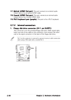
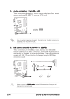
1 7 . O p t i c a l S / P D I F O u t p o r t. This port connects an external audio output device via an optical S/PDIF cable. 1 8 . C o a x i a l S / P D I F O u t p o r t . This port connects an external audio output device via a coaxial S/PDIF cable. 1 9 . P S / 2 k e y b o a r d p o r t ( p u r p l e ) . This port is for a PS/2 keyboard. 2.7.2 Internal connectors 1 . Floppy disk drive connector (34-1 pin FLOPPY) This connector is for the provided floppy disk drive (FDD) signal cable. Insert one end of the cable to this connector, then connect the other end to the signal connector at the back of the floppy disk drive. Pin 5 on the connector is removed to prevent incorrect cable connection when using a FDD cable with a covered Pin 5. FLOPPY NOTE: Orient the red markings on the floppy ribbon cable to PIN 1. P5N32-SLI ® gs PIN 1 P5N32-SLI Floppy disk drive connector 2-30 Chapter 2: Hardware information
-
 1
1 -
2
-
3
-
4
-
5
-
6
-
7
-
8
-
9
-
10
-
11
-
12
-
13
-
14
-
15
-
16
-
17
-
18
-
19
-
20
-
21
-
22
-
23
-
24
-
25
-
26
-
27
-
28
-
29
-
30
-
31
-
32
-
33
-
34
-
35
-
36
-
37
-
38
-
39
-
40
-
41
-
42
-
43
-
44
-
45
-
46
-
47
-
48
-
49
-
50
-
 51
51 -
 52
52 -
 53
53 -
 54
54 -
 55
55 -
 56
56 -
 57
57 -
 58
58 -
 59
59 -
 60
60 -
 61
61 -
62
-
63
-
64
-
65
-
66
-
67
-
68
-
69
-
70
-
71
-
72
-
73
-
74
-
75
-
76
-
77
-
78
-
79
-
80
-
81
-
82
-
83
-
84
-
85
-
86
-
87
-
88
-
89
-
90
-
91
-
92
-
93
-
94
-
95
-
96
-
97
-
98
-
99
-
100
-
101
-
102
-
103
-
104
-
105
-
106
-
107
-
108
-
109
-
110
-
111
-
112
-
113
-
114
-
115
-
116
-
117
-
118
-
119
-
120
-
121
-
122
-
123
-
124
-
125
-
126
-
127
-
128
-
129
-
130
-
131
-
132
-
133
-
134
-
135
-
136
-
137
-
138
-
139
-
140
-
141
-
142
-
143
-
144
-
145
-
146
-
147
-
148
-
149
-
150
-
151
-
152
-
153
-
154
-
155
-
156
-
157
-
158
-
159
-
160
-
161
-
162
-
163
-
164
-
165
-
166
-
167
-
168
-
169
-
170
-
171
-
172
-
173
-
174
-
175
-
176
-
177
-
178
 |
 |
