Asus P5N32-SLI-Deluxe P5N32-SLI Deluxe User's Manual for English Edition - Page 66
System power LED Green 3-pin PLED
 |
View all Asus P5N32-SLI-Deluxe manuals
Add to My Manuals
Save this manual to your list of manuals |
Page 66 highlights
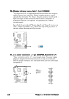
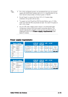
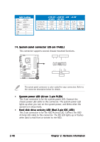
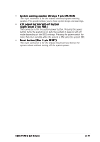
Light Loading CPU 3.8G PSC DDR667 1G*2 VGA 6600GT*2 HD SATA*2 CD-ROM 1 USB 2 PCI 1 Io_max (A) Io_rms (A) Vout (V) Po_max (W) +12V-V2 (4-pin) 10.29 8.364 12 123.48 +12V-V1 +5V (24-pin) 11.22 6.821 12 134.64 11.76 9.085 5 58.8 +3.3V 2.73 1.587 3.3 9.009 TOTAL PSU Po_max (W) 325.929 PLED+ PLED+5V Ground Ground Speaker P5N32-SLI IDE_LED+ IDE_LED- PWR Ground Reset Ground 14. System panel connector (20-pin PANEL) This connector supports several chassis-mounted functions. PLED SPEAKER PANEL ® IDE_LED RESET PWR * Requires an ATX power supply. P5N32-SLI System panel connector The sytem panel connector is color-coded for easy connection. Refer to the connector description below for details. • System power LED (Green 3-pin PLED) This 3-pin connector is for the system power LED. Connect the chassis power LED cable to this connector. The system power LED lights up when you turn on the system power, and blinks when the system is in sleep mode. • Hard disk drive activity LED (Red 2-pin IDE_LED) This 2-pin connector is for the HDD Activity LED. Connect the HDD Activity LED cable to this connector. The IDE LED lights up or flashes when data is read from or written to the HDD. 2-40 Chapter 2: Hardware information
-
 1
1 -
2
-
3
-
4
-
5
-
6
-
7
-
8
-
9
-
10
-
11
-
12
-
13
-
14
-
15
-
16
-
17
-
18
-
19
-
20
-
21
-
22
-
23
-
24
-
25
-
26
-
27
-
28
-
29
-
30
-
31
-
32
-
33
-
34
-
35
-
36
-
37
-
38
-
39
-
40
-
41
-
42
-
43
-
44
-
45
-
46
-
47
-
48
-
49
-
50
-
51
-
52
-
53
-
54
-
55
-
56
-
57
-
58
-
59
-
60
-
 61
61 -
 62
62 -
 63
63 -
 64
64 -
 65
65 -
 66
66 -
 67
67 -
 68
68 -
 69
69 -
 70
70 -
 71
71 -
72
-
73
-
74
-
75
-
76
-
77
-
78
-
79
-
80
-
81
-
82
-
83
-
84
-
85
-
86
-
87
-
88
-
89
-
90
-
91
-
92
-
93
-
94
-
95
-
96
-
97
-
98
-
99
-
100
-
101
-
102
-
103
-
104
-
105
-
106
-
107
-
108
-
109
-
110
-
111
-
112
-
113
-
114
-
115
-
116
-
117
-
118
-
119
-
120
-
121
-
122
-
123
-
124
-
125
-
126
-
127
-
128
-
129
-
130
-
131
-
132
-
133
-
134
-
135
-
136
-
137
-
138
-
139
-
140
-
141
-
142
-
143
-
144
-
145
-
146
-
147
-
148
-
149
-
150
-
151
-
152
-
153
-
154
-
155
-
156
-
157
-
158
-
159
-
160
-
161
-
162
-
163
-
164
-
165
-
166
-
167
-
168
-
169
-
170
-
171
-
172
-
173
-
174
-
175
-
176
-
177
-
178
 |
 |
