Bose Lifestyle 28 Installation guide - Page 11
Connecting the speakers to the Acoustimass, module - media center no power
 |
View all Bose Lifestyle 28 manuals
Add to My Manuals
Save this manual to your list of manuals |
Page 11 highlights
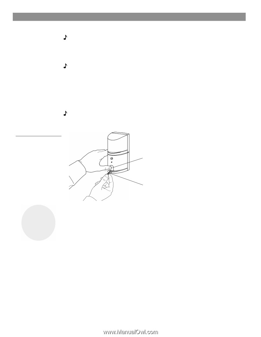
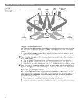
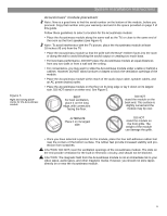
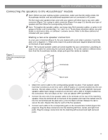
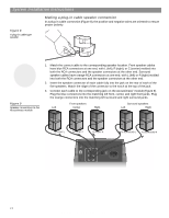
System Installation Instructions Connecting the speakers to the Acoustimass® module Note: Before you start making system connections, make sure that the media center, the Acoustimass module, and any additional equipment are not connected to AC power. The five dual-cube speakers that come with your system will either have a two-wire cable connector (Figure 7) or a plug-in cable connector (Figure 8 on page 12). Identify your type of speaker and then follow the corresponding instructions. Note: To lengthen the speaker cables, use heavy-duty RCA extension cables, or splice in 18gauge or thicker cord (connecting + to + and - to -). To purchase extension cables, see your dealer or electronics store, or call Bose® customer service. Refer to the Bose address list included with your system. Making a two-wire speaker connection In a two-wire connection (Figure 7), the wire marked with a red collar is positive (+) and the plain one is negative (-). These wires match the positive (red) and negative (black) terminals on the back of each speaker. Note: The surround speaker cables are joined together for your convenience, providing an easy-to-use cable for connecting the surround speakers. To run the cables in different directions from the Acoustimass module, simply pull apart the cables as needed. Figure 7 A two-wire connection type speaker Terminal tab 3 Red (+) wire 1. Match the correct cable to the corresponding speaker location. Front speaker cables have blue connectors at one end, with L (left), R (right), or C (center) molded into the connectors. The red collars on the + wire are labeled LEFT, RIGHT, and CENTER. Surround speaker cables have orange connectors at one end, with L (left) or R (right) molded into the connectors. The red collars on the + wire are labeled LEFT and RIGHT. 2. Connect the wire end of one speaker cable to the terminals on the rear of the matching speaker. Press the terminal tab on the back of the speaker and insert the marked wire (+) into the red terminal and the plain wire (-) into the black terminal. Release the tab to secure the wire. Repeat this step for each of the five speakers. 3. Connect each cable to the corresponding jack on the Acoustimass module (Figure 9on page 12). Plug the blue connectors into the matching left front, center, and right front jacks. Plug the orange connectors into the matching left surround and right surround jacks. 11 AM259777_02_V.pdf • April 23, 2002
-
 1
1 -
2
-
3
-
4
-
5
-
 6
6 -
 7
7 -
 8
8 -
 9
9 -
 10
10 -
 11
11 -
 12
12 -
 13
13 -
 14
14 -
 15
15 -
 16
16 -
17
-
18
-
19
-
20
-
21
-
22
-
23
-
24
-
25
-
26
-
27
-
28
-
29
-
30
-
31
-
32
 |
 |