Bose Lifestyle 28 Installation guide - Page 16
Connecting your VCR to the system optional - 35
 |
View all Bose Lifestyle 28 manuals
Add to My Manuals
Save this manual to your list of manuals |
Page 16 highlights
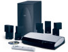
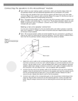
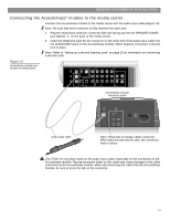
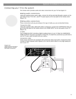
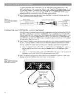
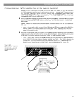
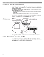
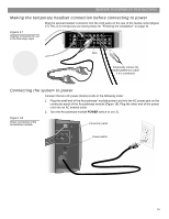
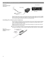
System Installation Instructions Figure 13 Component video adapter connections To make component video connections, you will need video-grade cables for the Y, Pb, and Pr jacks and the Bose® component video adapter (Figure 13). This adapter plugs into the S-VIDEO and COMPOSITE outputs. Your system will send the correct signals to these jacks when you change the video output setting to YPbPr. See your LIFESTYLE® 28/35 system operating guide for instructions on how to change system settings. Note: Component video jacks are often color-coded and it is essential that you match the color-coded connections with the cables. Media Center S-VIDEO OUTPUT COMPOSITE VIDEO OUTPUT Component video adapter Your TV Pr (Red) Y (Green) Pb (Blue) Connecting your VCR to the system (optional) The type of video connection used with your TV must match the type of connection used with your VCR, if you choose to connect it to the system. If you connected your TV to the COMPOSITE VIDEO OUTPUT, connect your VCR output to the COMPOSITE VIDEO INPUT. If you connected your TV to the S-VIDEO OUTPUT, connect your VCR to the S-VIDEO INPUT. If your VCR does not have an S-VIDEO output, you may be able to connect your VCR composite video output directly to your TV. Note: If your VCR did not come with the stereo audio and video cables required to connect it to your LIFESTYLE® system, contact your local electronics store or authorized Bose dealer. The rear panel of the media center provides audio and video connections for your VCR. 1. Using the supplied stereo audio cable, connect the left (L) and right (R) audio outputs on the rear panel of your VCR to the L and R VCR audio inputs on the rear panel of the media center. 2. Using the supplied video cable, connect the COMPOSITE video input on the rear panel of the media center to the VIDEO OUT on the rear panel of your VCR. Note: You should not connect the video output of your LIFESTYLE ® system to a VCR, since playing copy-protected DVDs may result in poor picture quality. Figure 14 Media center-to-VCR video and audio connections TV SENSOR IR EMITTER SERIAL DATA 33V DC POWER 1.1A RECORD TAPE AUX VCR TV AM L L L L L FM 75 ANTENNA 1 OPTICAL OPTICAL R R R R R VIDEO INPUTS COMPOSITE S-VIDEO 2 SPEAKER ZONES INPUT OUTPUT DIGITAL AUDIO OUTPUTS DIGITAL DIGITAL DIGITAL AUDIO INPUTS DIGITAL COMPOSITE S-VIDEO VIDEO OUTPUTS VCR connector panel AUDIO OUT VIDEO OUT R L VCR 16 AM259777_02_V.pdf • April 23, 2002
-
 1
1 -
2
-
3
-
4
-
5
-
6
-
7
-
8
-
9
-
10
-
 11
11 -
 12
12 -
 13
13 -
 14
14 -
 15
15 -
 16
16 -
 17
17 -
 18
18 -
 19
19 -
 20
20 -
 21
21 -
22
-
23
-
24
-
25
-
26
-
27
-
28
-
29
-
30
-
31
-
32
 |
 |