Bose Lifestyle 28 Installation guide - Page 17
Connecting your cable/satellite box to the system optional - ir
 |
View all Bose Lifestyle 28 manuals
Add to My Manuals
Save this manual to your list of manuals |
Page 17 highlights
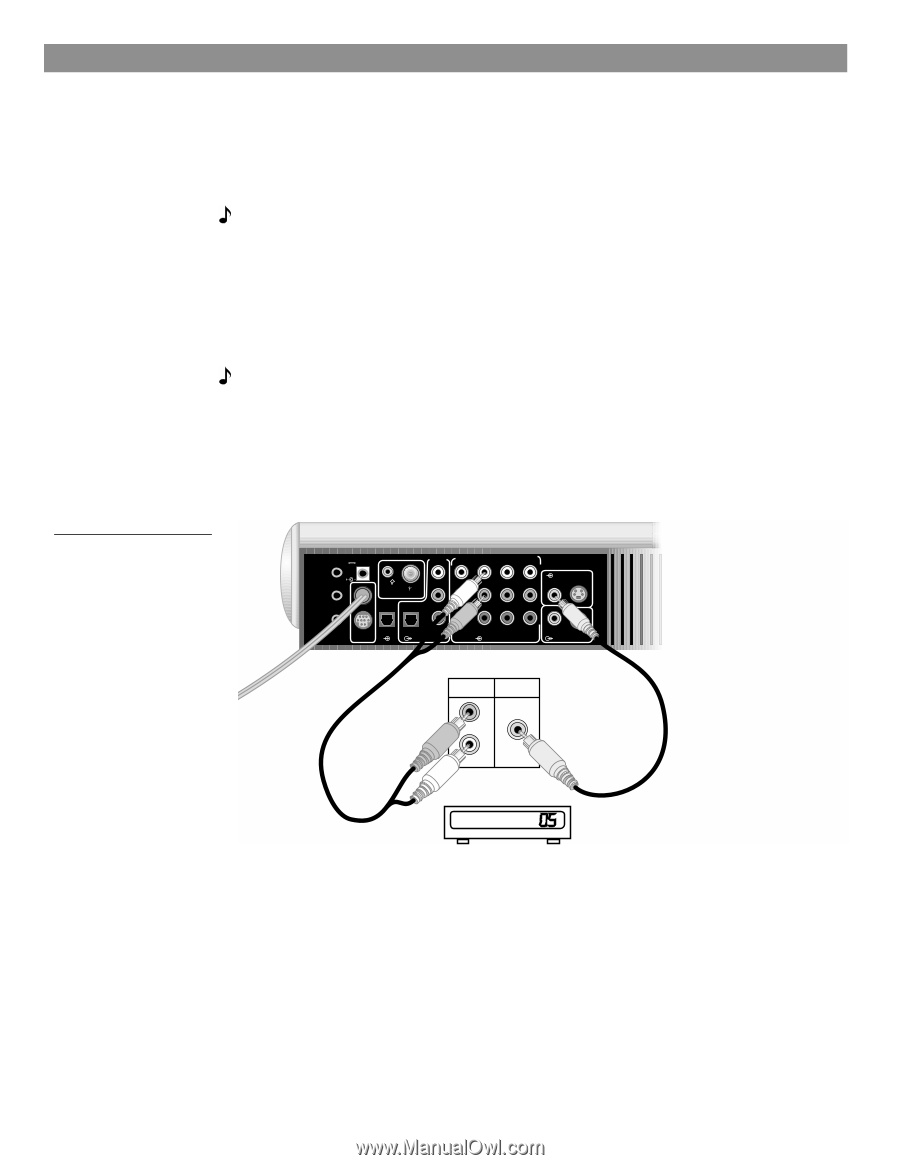
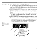
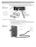
System Installation Instructions Connecting your cable/satellite box to the system (optional) The type of video connection used with your TV and VCR must match the type of connection used with your cable/satellite box, if you choose to connect it to the system. If you connected your TV to the COMPOSITE VIDEO OUTPUT, connect your cable/satellite box output to the COMPOSITE VIDEO INPUT. If you connected your TV to the S-VIDEO OUTPUT, connect your cable/satellite box to the S-VIDEO INPUT. Note: If your cable/satellite box did not come with the stereo audio and video cables required to connect it to your LIFESTYLE® system, contact your local electronics store or authorized Bose dealer. The rear panel of the media center provides audio and video connections for your cable/satellite box. 1. Using a stereo audio cable, connect the left (L) and right (R) audio outputs (if available) on the rear panel of your cable/satellite box to the L and R AUX audio inputs on the rear panel of the media center. Note: For convenience, until your system is completely installed and tested, you may want to postpone making this connection to the media center AUX jacks. The AUX jacks are required for use with a temporary headset connection during the final installation steps. 2. Using a video cable, connect the VIDEO OUT on the rear panel of your cable/satellite box to the COMPOSITE video input on the rear panel of your VCR. If your VCR is already connected there, you may instead connect the VIDEO OUT from your cable/satellite box directly to your media center's COMPOSITE video input (as shown in Figure 15). Figure 15 Media center-to-cable/satellite box video and audio connections (if VCR not used) TV SENSOR IR EMITTER SERIAL DATA 33V DC POWER 1.1A RECORD TAPE AUX VCR TV AM L L L L L FM 75 ANTENNA 1 OPTICAL OPTICAL R R R R R VIDEO INPUTS COMPOSITE S-VIDEO 2 SPEAKER ZONES INPUT OUTPUT DIGITAL AUDIO OUTPUTS DIGITAL DIGITAL DIGITAL AUDIO INPUTS DIGITAL COMPOSITE S-VIDEO VIDEO OUTPUTS AUDIO OUT R L VIDEO OUT Cable/satellite box connector panel Cable/satellite box 17 AM259777_02_V.pdf • April 23, 2002
-
 1
1 -
2
-
3
-
4
-
5
-
6
-
7
-
8
-
9
-
10
-
11
-
 12
12 -
 13
13 -
 14
14 -
 15
15 -
 16
16 -
 17
17 -
 18
18 -
 19
19 -
 20
20 -
 21
21 -
 22
22 -
23
-
24
-
25
-
26
-
27
-
28
-
29
-
30
-
31
-
32
 |
 |