Bose Lifestyle 28 Installation guide - Page 13
Connecting the Acoustimass, module to the media center - optical input
 |
View all Bose Lifestyle 28 manuals
Add to My Manuals
Save this manual to your list of manuals |
Page 13 highlights
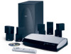
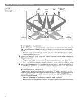
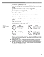
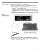
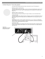
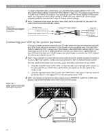
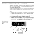
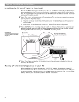
System Installation Instructions Connecting the Acoustimass® module to the media center Connect the Acoustimass module to the media center with the audio input cable (Figure 10). Note: Be sure that each connector is fully inserted into each jack. 1. Plug the small black multi-pin connector (flat side facing up) into the SPEAKER ZONES jack labeled "1" on the back of the media center. 2. Insert the telephone-style RJ-45 connector on the other end of the audio input cable into the AUDIO INPUT jack on the Acoustimass module. When properly connected, it should lock in place. Note: Refer to "Setting up a second listening zone" on page 25 for information on connecting a second zone. Figure 10 Acoustimass module connection to media center TV SENSOR IR EMITTER SERIAL DATA 33V DC POWER 1.1A RECORD TAPE AUX VCR TV AM L L L L L FM 75 ANTENNA 1 1 OPTICAL OPTICAL R R R R R VIDEO INPUTS COMPOSITE S-VIDEO 2 SPEAKER ZONES INPUT OUTPUT DIGITAL AUDIO OUTPUTS DIGITAL DIGITAL DIGITAL AUDIO INPUTS DIGITAL COMPOSITE S-VIDEO VIDEO OUTPUTS Acoustimass module connector panel AUDIO INPUT OUTPUTS TO CUBE SPEAKERS FRONT SURROUND L C L R R POWER 100-120/200-240V AC 50/60 Hz 350W MAX. Audio input cable Note: Press tab to release cable connector. When fully inserted into the jack, the connector locks in place. CAUTION: Do not place strain on the audio input cable, especially on the connection to the Acoustimass module. Placing excessive strain on the cable may cause damage to the cable connection at the Acoustimass module. When disconnecting the cable from the Acoustimass module, be sure to press the tab on the connector. 13 AM259777_02_V.pdf • April 23, 2002
-
 1
1 -
2
-
3
-
4
-
5
-
6
-
7
-
 8
8 -
 9
9 -
 10
10 -
 11
11 -
 12
12 -
 13
13 -
 14
14 -
 15
15 -
 16
16 -
 17
17 -
 18
18 -
19
-
20
-
21
-
22
-
23
-
24
-
25
-
26
-
27
-
28
-
29
-
30
-
31
-
32
 |
 |