Bose Lifestyle 28 Installation guide - Page 14
Connecting the antennas - receiver
 |
View all Bose Lifestyle 28 manuals
Add to My Manuals
Save this manual to your list of manuals |
Page 14 highlights
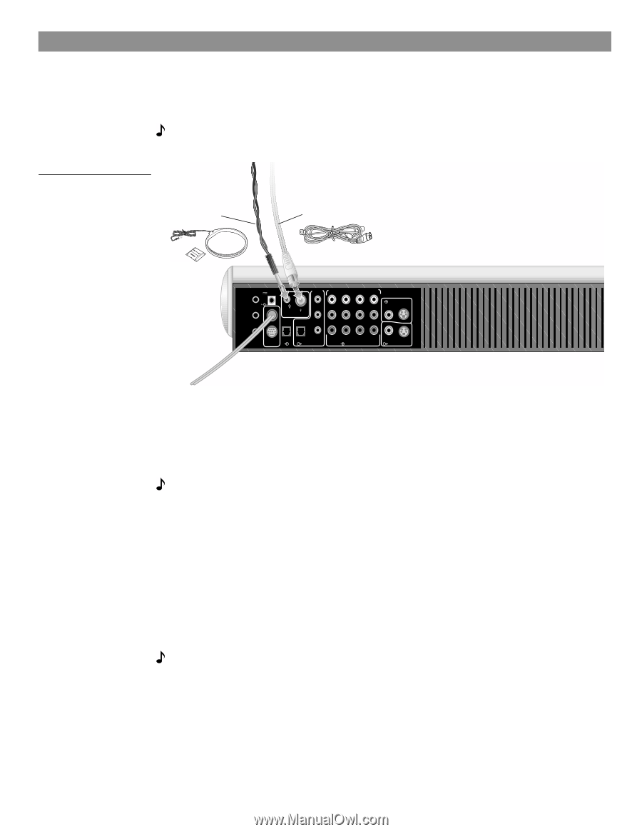
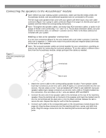
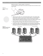
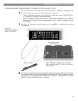
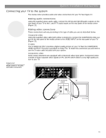
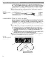
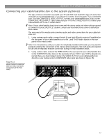
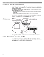
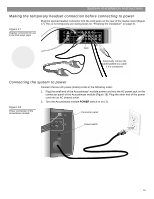
System Installation Instructions Connecting the antennas The rear panel of the media center provides connections for AM and FM antennas (Figure 11). Be sure to unwrap the bundled antenna wires and straighten them as much as possible to ensure the best reception. Note: Outdoor antennas may be used. To install an outdoor antenna, consult a qualified installer. Follow all safety instructions supplied with the antenna. Figure 11 Connections for the AM and FM antennas AM antenna lead FM dipole antenna lead TV SENSOR IR EMITTER SERIAL DATA 33V DC POWER 1.1A RECORD TAPE AUX VCR TV AM L L L L L FM 75 ANTENNA 1 OPTICAL OPTICAL R R R R R VIDEO INPUTS COMPOSITE S-VIDEO 2 SPEAKER ZONES INPUT OUTPUT DIGITAL AUDIO OUTPUTS DIGITAL DIGITAL DIGITAL AUDIO INPUTS DIGITAL COMPOSITE S-VIDEO VIDEO OUTPUTS Connecting an FM antenna Plug the connector on the FM dipole antenna lead into the FM antenna jack. Spread out the antenna arms. Change the orientation of the antenna arms to get optimum FM reception. Place the antenna as far from the media center and other components as possible. Connecting the AM antenna Note: To mount the AM antenna on a wall, follow the instructions enclosed with the antenna. 1. Plug the connector on the AM antenna lead into the AM antenna jack. 2. Stand the loop antenna on the base, following the instructions enclosed with the AM antenna. 3. Move the AM loop antenna as far as possible, at least 20 inches (50 cm), from the media center, and at least 2 feet (60 cm) from the Acoustimass® module. Experiment with the orientation of the loop for optimum AM reception. Connecting to a cable radio provider Some cable TV providers make FM radio signals available through the cable service to your home. This connection is made to the external FM jack on the back panel of the media center. To connect to this service, contact your cable TV provider for assistance. Note: Make sure that the cable radio installation includes a signal splitter so that only the FM radio band, not the cable TV band, is received by the media center. If necessary, contact a qualified installer. 14 AM259777_02_V.pdf • April 23, 2002
-
 1
1 -
2
-
3
-
4
-
5
-
6
-
7
-
8
-
 9
9 -
 10
10 -
 11
11 -
 12
12 -
 13
13 -
 14
14 -
 15
15 -
 16
16 -
 17
17 -
 18
18 -
 19
19 -
20
-
21
-
22
-
23
-
24
-
25
-
26
-
27
-
28
-
29
-
30
-
31
-
32
 |
 |