Bose Lifestyle 28 Installation guide - Page 15
Connecting your TV to the system - audio input cable
 |
View all Bose Lifestyle 28 manuals
Add to My Manuals
Save this manual to your list of manuals |
Page 15 highlights
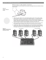
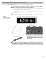
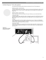
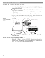
System Installation Instructions Connecting your TV to the system The media center provides audio and video connections for your TV. See Figure 12. 4 Figure 12 Media center-to-TV video and audio connections Making audio connections Using the supplied stereo audio cable, connect the left (L) and right (R) audio outputs on the rear panel of your TV to the L and R TV audio inputs on the rear panel of the media center (Figure 12). Making video connections These connections will vary according to the type of cable you use as described below. Composite video Using the supplied video cable (with yellow connectors), connect the COMPOSITE video output on the rear panel of the media center to the VIDEO INPUT on the rear panel of your TV (Figure 12). S-video The S-VIDEO OUTPUT provides a higher quality picture on your TV than the COMPOSITE VIDEO OUTPUT. This jack is provided on many TVs. To make this connection you will need to use the S-video cable included with your system. Component video Some newer televisions are equipped with component video input jacks. Component video consists of three separate video signals (Y, Pb, and Pr) which deliver a very high quality picture to your TV. TV SENSOR IR EMITTER SERIAL DATA 33V DC POWER 1.1A RECORD TAPE AUX VCR TV AM L L L L L FM 75 ANTENNA 1 OPTICAL OPTICAL R R R R R VIDEO INPUTS COMPOSITE S-VIDEO 2 SPEAKER ZONES INPUT OUTPUT DIGITAL AUDIO OUTPUTS DIGITAL DIGITAL DIGITAL AUDIO INPUTS DIGITAL COMPOSITE S-VIDEO VIDEO OUTPUTS TV connector panel AUDIO OUT VIDEO IN TV R L 15 AM259777_02_V.pdf • April 23, 2002
-
 1
1 -
2
-
3
-
4
-
5
-
6
-
7
-
8
-
9
-
 10
10 -
 11
11 -
 12
12 -
 13
13 -
 14
14 -
 15
15 -
 16
16 -
 17
17 -
 18
18 -
 19
19 -
 20
20 -
21
-
22
-
23
-
24
-
25
-
26
-
27
-
28
-
29
-
30
-
31
-
32
 |
 |
