Bose Lifestyle 28 Installation guide - Page 12
Making a plug-in cable speaker connection - acoustimass module
 |
View all Bose Lifestyle 28 manuals
Add to My Manuals
Save this manual to your list of manuals |
Page 12 highlights
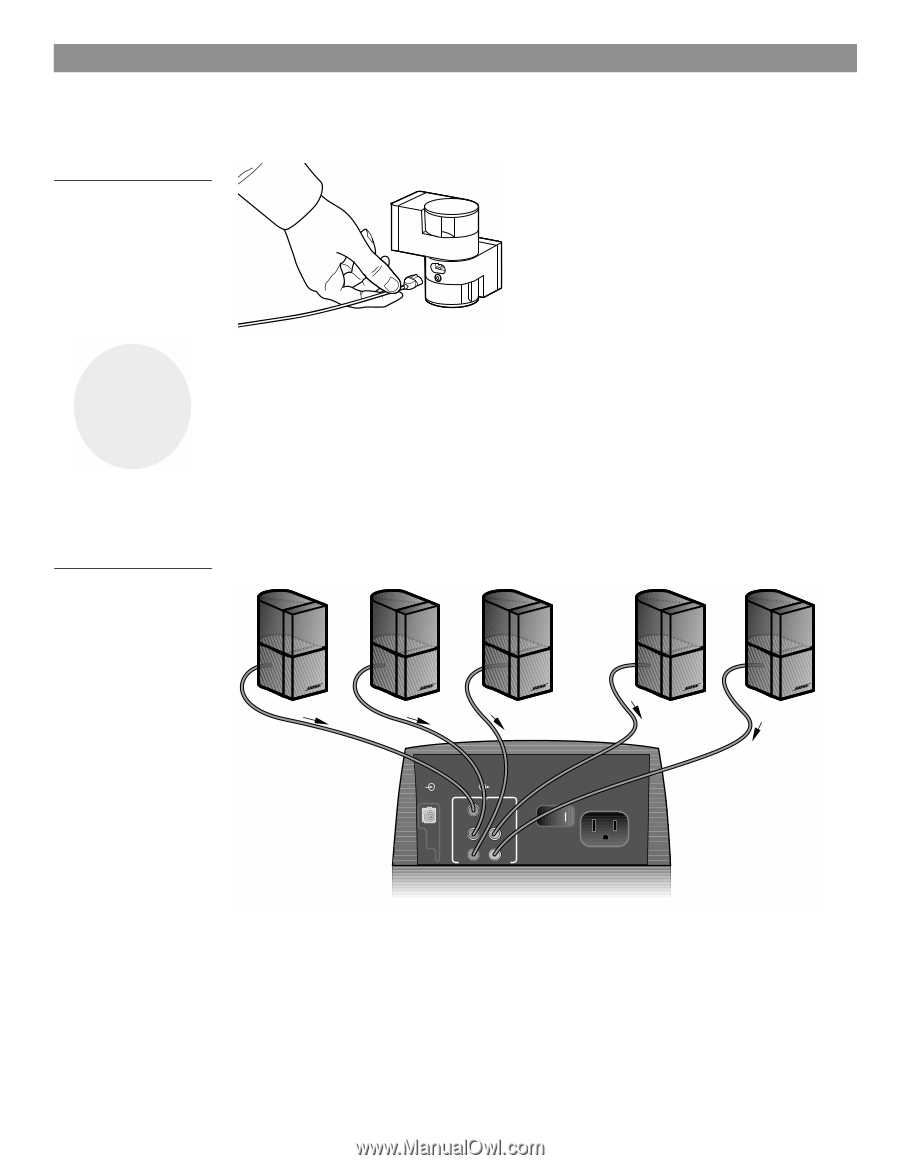
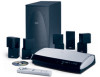
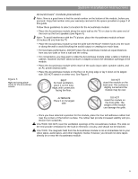
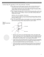
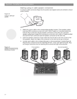
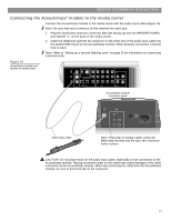
System Installation Instructions Figure 8 A plug-in cable type speaker Making a plug-in cable speaker connection In a plug-in cable connection (Figure 8), the positive and negative wires are oriented to ensure proper polarity. 3 Figure 9 Speaker connections to the Acoustimass module 1. Match the correct cable to the corresponding speaker location. Front speaker cables have blue RCA connectors at one end, with L (left), R (right), or C (center) molded into both the RCA connectors and the speaker connectors at the other end. Surround speaker cables have orange RCA connectors at one end, with L (left) or R (right) molded into both the RCA connectors and the speaker connectors at the other end. 2. Insert the speaker connector of each cable fully into the jack on the rear of each of the five speakers. Match the ridge of the connector to the notch at the top of the jack. 3. Connect each cable to the corresponding jack on the Acoustimass® module (Figure 9). Plug the blue connectors into the matching left front, center, and right front jacks. Plug the orange connectors into the matching left surround and right surround jacks. Front speakers Left Center Right Surround speakers Left Right To FRONT L To FRONT C To FRONT R To SURROUND L To SURROUND R AUDIO INPUT OUTPUTS TO CUBE SPEAKERS FRONT SURROUND L C L R R POWER 100-120/200-240V AC 50/60 Hz 350W MAX. 12 AM259777_02_V.pdf • April 23, 2002
-
 1
1 -
2
-
3
-
4
-
5
-
6
-
 7
7 -
 8
8 -
 9
9 -
 10
10 -
 11
11 -
 12
12 -
 13
13 -
 14
14 -
 15
15 -
 16
16 -
 17
17 -
18
-
19
-
20
-
21
-
22
-
23
-
24
-
25
-
26
-
27
-
28
-
29
-
30
-
31
-
32
 |
 |